
Welcome to Part 7 of the blog series on vSphere supervisor networking with NSX and AVI. This is the final vSphere namespace topology that we are going to discuss, where we have a dedicated T0 VRF gateway for the namespace. This topology is almost similar to our previous article with dedicated T0 gateways, but with few routing changes that we will discuss towards the end of this article. If you missed any of the previous articles on namespace topologies, please check out from the links below:
Part 4: vSphere namespace with network inheritance
https://vxplanet.com/2025/05/15/vsphere-supervisor-networking-with-nsx-and-avi-part-4-vsphere-namespace-with-network-inheritance/
Part 5: vSphere namespace with custom Ingress and Egress network
https://vxplanet.com/2025/05/16/vsphere-supervisor-networking-with-nsx-and-avi-part-5-vsphere-namespace-with-custom-ingress-and-egress-network/
Part 6: vSphere namespace with dedicated T0 gateways
https://vxplanet.com/2025/05/16/vsphere-supervisor-networking-with-nsx-and-avi-part-6-vsphere-namespace-with-dedicated-t0-gateway/
Let’s get started:
vSphere Namespace with Dedicated T0 VRF Gateway
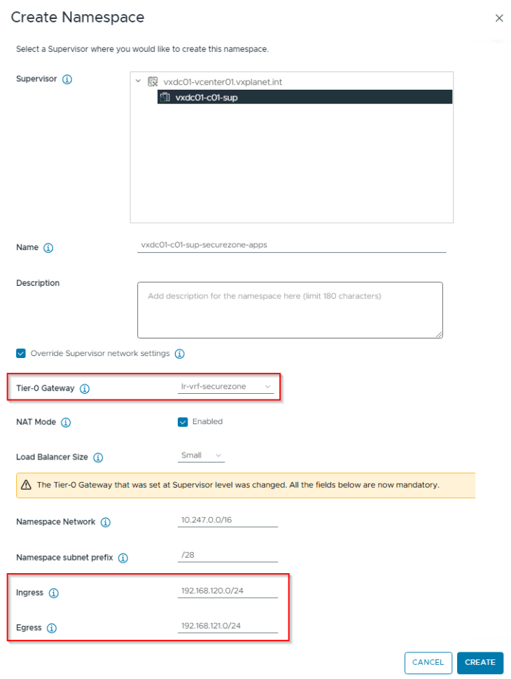
In this vSphere namespace topology, we will override all the network settings from the vSphere supervisor (similar to the previous article, Part 6), because overriding the T0 gateway at the namespace level with a custom T0 / VRF gateway will require unique values for namespace network, ingress and egress CIDRs.
- T0 Gateway
- Workload / Namespace CIDR
- Ingress CIDR
- Egress CIDR (if NAT mode is enabled)
- NAT mode
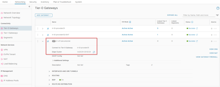
We have a VRF gateway “lr-vrf-securezone” created under the provider T0 gateway that will be used to host applications for a secure zone. This VRF gateway has upstream routing to a secure zone through a specific routing path having access security controls, just a fictitious use case for creating the new namespace.
Let’s login to vCenter Workload Management and create a vSphere namespace for the secure zone, making sure the flag for “Override supervisor network settings” is checked, the custom VRF gateway is selected and that the fields for namespace network, Ingress and Egress CIDR are updated with custom values.
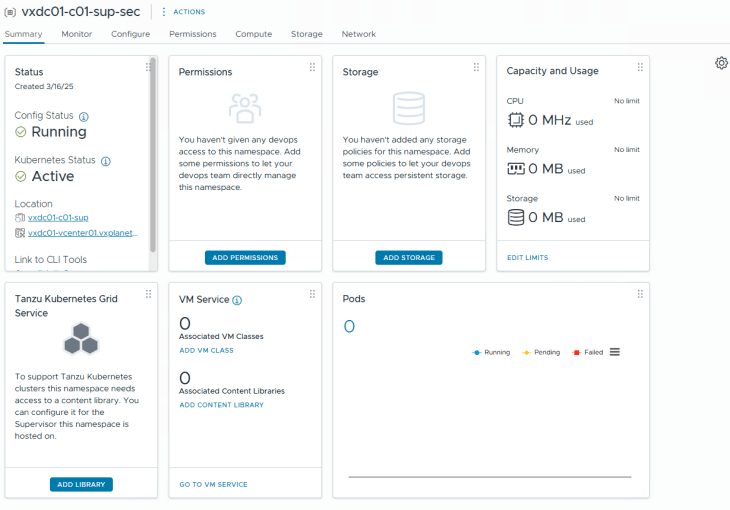
After basic namespace configuration (permissions, storage class, VM Class assignments etc,) we should have the vSphere namespace up and running.
Reviewing NSX objects
Now let’s review the NSX objects that are created by the workflow.
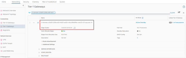
Like all the previous topologies, a dedicated T1 gateway is created for the vSphere namespace, however this T1 gateway is up streamed to the VRF gateway “lr-vrf-securezone“ that was specified during the namespace creation workflow.
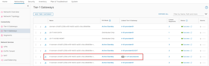
This T1 gateway is instantiated on the same edge cluster as the VRF gateway “VxDC01-C01-EC01”.
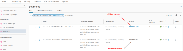
Similar to the previous topologies, two default segments are created, both attached to the namespace T1 gateway. We also have additional dedicated segments for each TKG service cluster that is created under the vSphere namespace, all up streamed to the same namespace T1 gateway.
- Namespace network : This is where the vSphere pods attach to. This network is carved out from the namespace network specified in the vSphere namespace creation workflow (10.247.0.0/16)
- AVI data segment : This is a non-routable subnet on the CGNAT range and has DHCP enabled. This is where the AVI SE data interfaces attach to. A dedicated interface on the SEs from the same SE Group for the supervisor will be consumed for each vSphere namespace that is created.
- TKG Service cluster network: This is where TKG service clusters attach to. One segment will be created for each TKG service cluster. This network is carved out from the namespace network (10.247.0.0/16) specified in the vSphere namespace creation workflow.
Note that for this article, we haven’t deployed any TKG service clusters as we don’t have any networking changes specific to TKG service clusters to highlight. Like the previous article, we have an interesting section on routing considerations that must be accomplished before spinning up any TKG service clusters, and will discuss towards the end of this article.
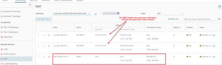
Since we have created the vSphere namespace with NAT mode enabled, we have an SNAT rule created under the namespace T1 gateway for outbound communication. This SNAT IP is taken from the Egress CIDR that we specified during the namespace creation workflow. Note that east-west communication between supervisor and vSphere namespaces will always happen with No-SNAT (We should see no-SNAT rules under the T1 gateways of supervisor and vSphere namespaces).
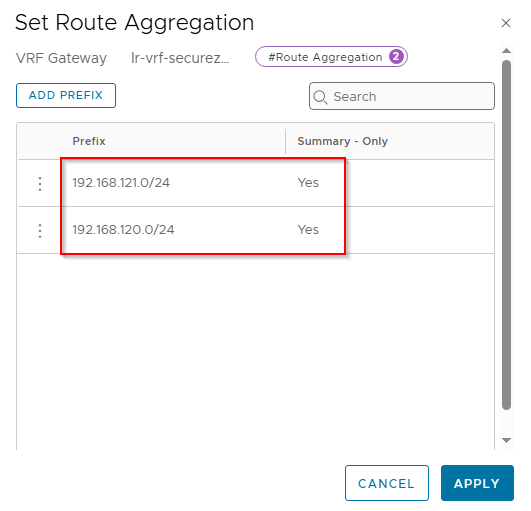
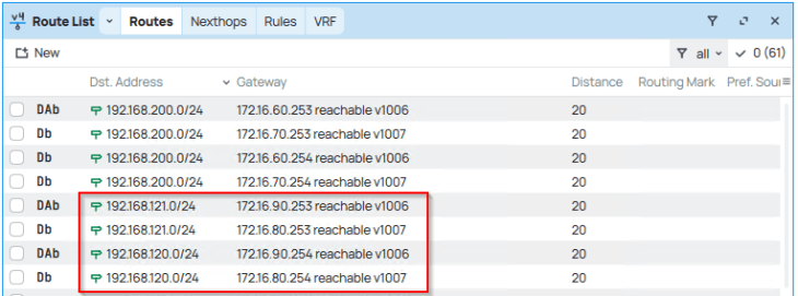
Because we advertised the new Ingress and Egress networks from the VRF gateway with route aggregation, we see the summary route in the TOR physical fabrics.
Reviewing AVI objects
Now let’s review the AVI objects that are created by the workflow.
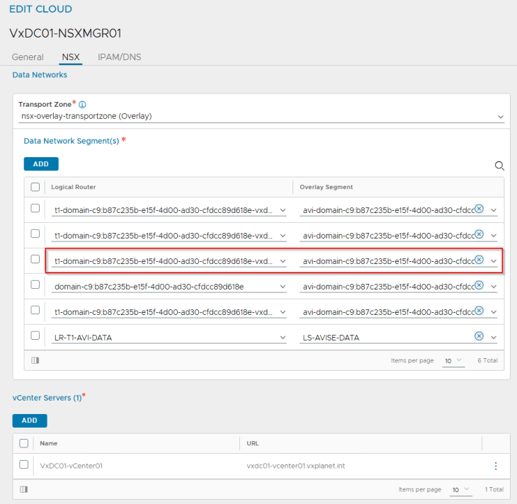
The dedicated T1 gateway created for the vSphere namespace and the respective AVI data segment will be added by the workflow as data networks to the AVI cloud connector.
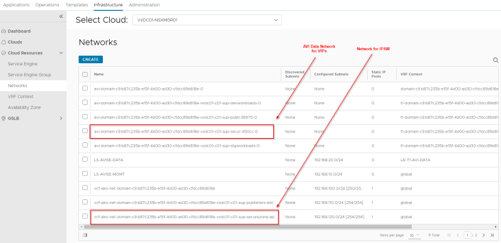
We will see two networks:
- AVI data network: This is where the AVI SE data interface for this vSphere namespace attach to. DHCP is enabled on this data network (through segment DHCP in NSX)
- VIP network: Because we are overriding the network settings from the supervisor with a custom Ingress network, we should see a new IPAM network created and added to the NSX cloud connector.
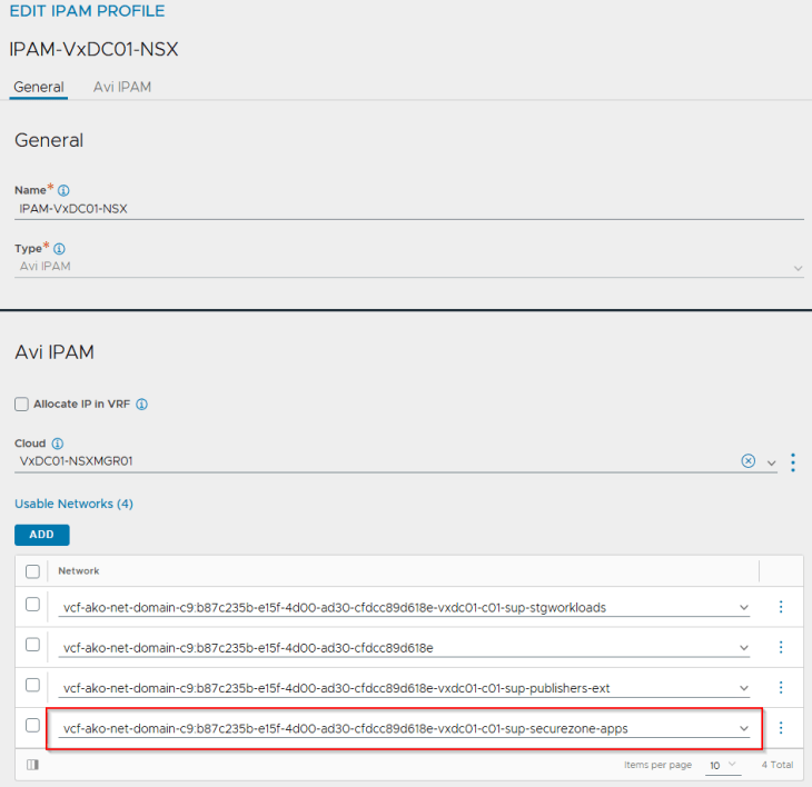
In the IPAM profile, we should now see four networks:
- one for the supervisor and all vSphere namespaces inhering network settings from the supervisor, which we discussed in Part 3 and Part 4
- the second for vSphere namespaces with a custom Ingress network, which we discussed in Part 5
- the third for vSphere namespaces with a custom T0 gateway and Ingress network, which we discussed in Part 6.
- and the fourth for vSphere namespaces with a custom VRF gateway, that we are just created in this article.
Routing considerations between vSphere supervisor and vSphere namespace with custom VRF gateway
One of the routing requirements between the vSphere namespaces and the vSphere supervisor is that they need to be able to communicate with each other without NAT. Hence if this requirement is not met, we won’t be able to successfully deploy a TKG service cluster in the vSphere namespace.
We have the below scenarios where the vSphere supervisor and vSphere namespaces with custom VRF gateway is deployed:
- Both vSphere supervisor and vSphere namespace are in no-NAT mode
- vSphere supervisor is in no-NAT mode and vSphere namespace is in NAT mode
- vSphere supervisor is in NAT mode and vSphere namespace is in no-NAT mode
- Both vSphere supervisor and vSphere namespace are in NAT mode
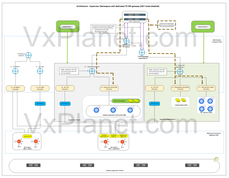
Scenario 1 (Both vSphere supervisor and vSphere namespace in no-NAT mode)
In this scenario, NAT mode is not used in supervisor and vSphere namespaces, hence supervisor workload network, namespace network and TKG cluster networks are advertised northbound from the T0 and VRF gateways to the physical fabrics. Routing between the vSphere namespace and the vSphere supervisor happens on the physical fabrics without SNAT, as shown in the below topology, and hence no additional routing configuration is required.
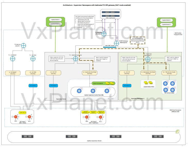
Scenario 2 (Both vSphere supervisor and vSphere namespace OR either of them in NAT mode)
In this scenario, the physical fabrics doesn’t have reachability information to either of them or both and requires additional routing configuration to allow no-SNAT communication between the vSphere namespaces and the vSphere supervisor.
Because the vSphere namespace networks and vSphere supervisor networks are under different gateways (T0 and VRF gateway) with either of them or both not advertising the networks upstream, how do they communicate to each other?
The answer is Inter-VRF routing. Inter-VRF routing allows the supervisor and namespace networks to be advertised between each other over an internally plumbed Inter-VRF transit link (analogous to the inter-T0 transit link that we created in the previous article), as shown below:
Let’s implement this:
Inter-VRF routing between provider T0 gateway (supervisor) and VRF gateway (vSphere namespace)
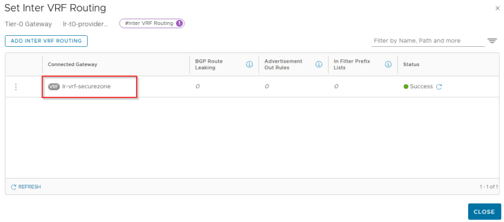
Let’s enable inter-VRF routing on the VRF gateway towards the provider T0 gateway:
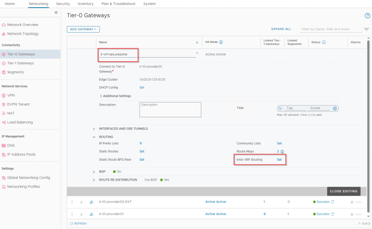
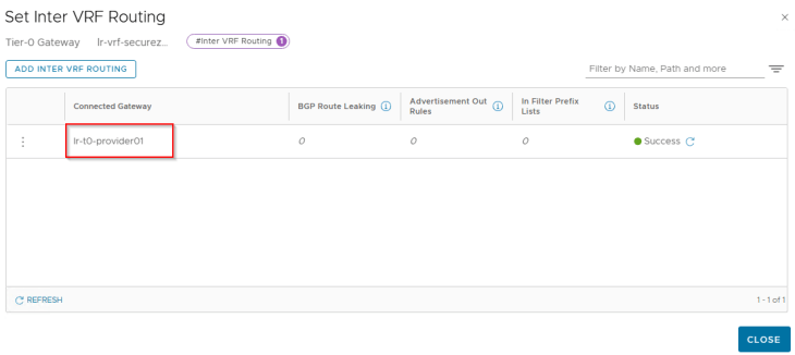
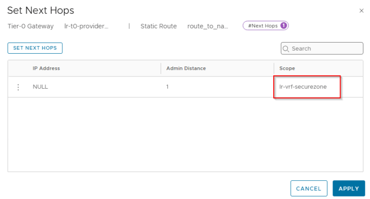
Similarly, we configure inter-VRF routing on the provider T0 gateway towards the VRF gateway:
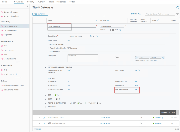
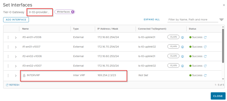
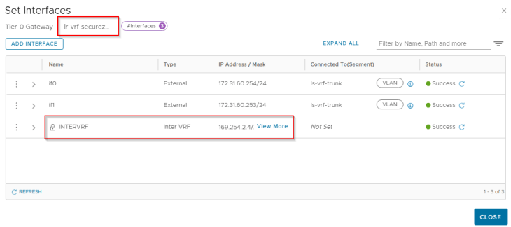
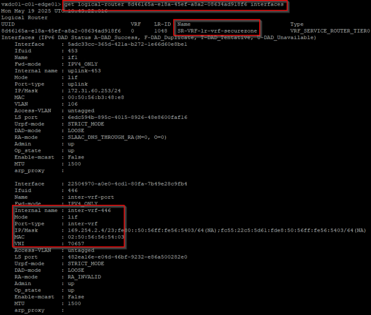
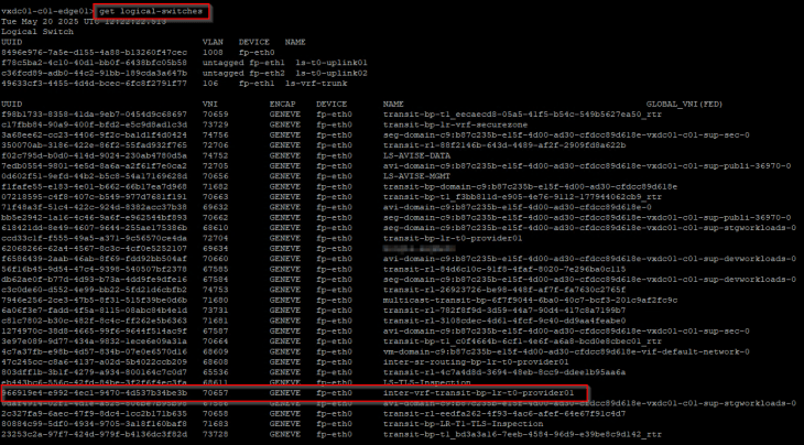
At this moment, we see an internal interface “INTERVRF” on both the provider and VRF gateways attached to an internally plumbed overlay segment.
Let’s login to the edge cli for the VRF gateway and verify the inter-vrf transit segment and interface attachment.
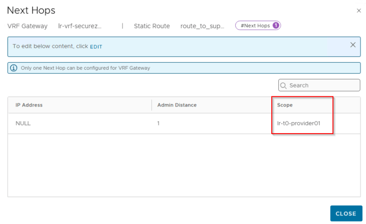
Now let’s configure static routes on the VRF gateway to reach the supervisor network and VIP network from the vSphere namespace segments.
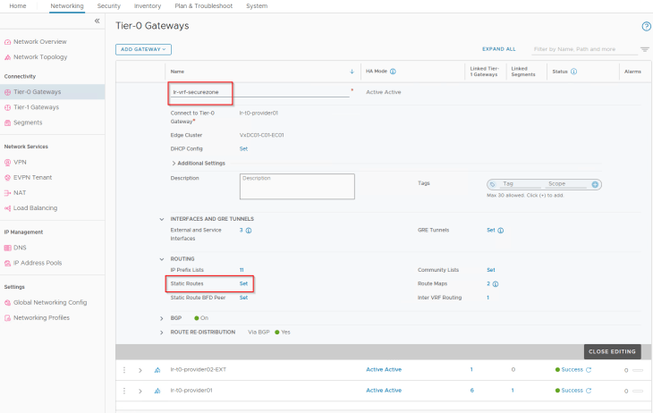
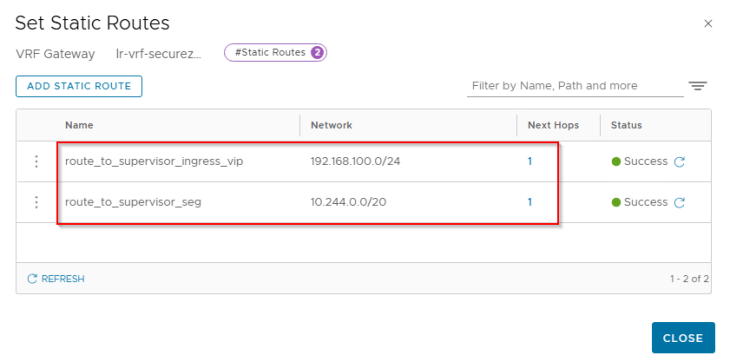
Note that, to configure this inter-VRF static route we need to set scope as destination VRF (Provider T0) and keep the next hop IP as blank.
Similarly, we need static routes on the provider T0 gateway to reach the vSphere namespace network and VIP network from the supervisor workload segment.
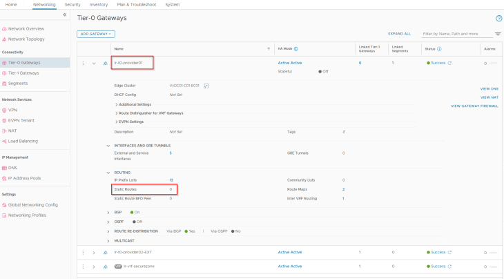
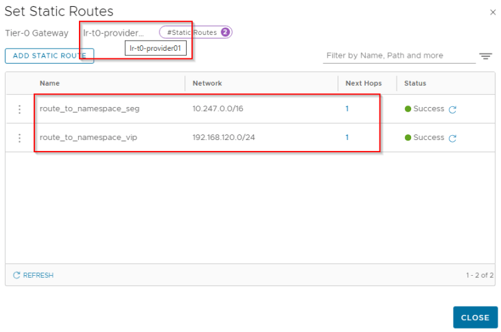
And we set the next-hop scope as destination VRF (VRF gateway).
At this moment, we should see that connectivity is established between the supervisor segment (under the provider T0 gateway) and the vSphere namespace segment (under the VRF gateway).
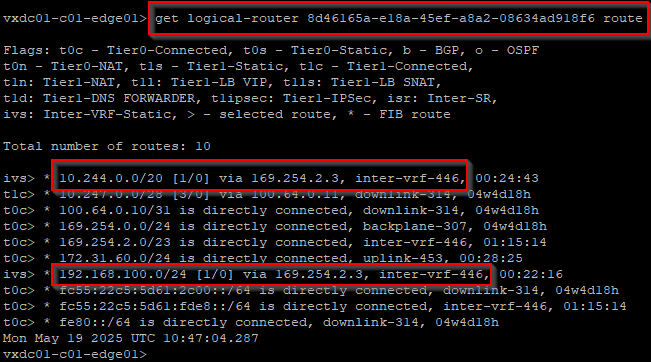
Below is the routing table from the VRF gateway (SR construct) and we see Inter-VRF static routes (labelled as “ivs”) to the supervisor networks (10.244.0.0/20 and 192.168.100.0/24)
We should now be good to deploy TKG service clusters in the vSphere namespace.
For more information on NSX Inter-VRF routing and the import / export policies, please check out the official documentation below:
https://techdocs.broadcom.com/us/en/vmware-cis/nsx/vmware-nsx/4-2/administration-guide/tier-0-gateways/tier-0-vrf-gateways/inter-vrf-routing.html
Excellent, we have now reached the end of this article. The next chapters on this blog series are around multiple supervisor clusters and their topologies, and I would need to scale out my home lab with additional resources to build out multiple supervisor clusters. I hope to be back soon.
Stay tuned!!!
I hope this article was informative. Thanks for reading

Continue reading? Here are the other chapters of this series:
Part 1: Architecture and Topologies
https://vxplanet.com/2025/04/16/vsphere-supervisor-networking-with-nsx-and-avi-part-1-architecture-and-topologies/
Part 2: Environment Build and Walkthrough
https://vxplanet.com/2025/04/17/vsphere-supervisor-networking-with-nsx-and-avi-part-2-environment-build-and-walkthrough/
Part 3: AVI onboarding and Supervisor activation
https://vxplanet.com/2025/04/24/vsphere-supervisor-networking-with-nsx-and-avi-part-3-avi-onboarding-and-supervisor-activation/
Part 4: vSphere namespace with network inheritance
https://vxplanet.com/2025/05/15/vsphere-supervisor-networking-with-nsx-and-avi-part-4-vsphere-namespace-with-network-inheritance/
Part 5: vSphere namespace with custom Ingress and Egress network
https://vxplanet.com/2025/05/16/vsphere-supervisor-networking-with-nsx-and-avi-part-5-vsphere-namespace-with-custom-ingress-and-egress-network/
Part 6: vSphere namespace with dedicated T0 gateways
https://vxplanet.com/2025/05/16/vsphere-supervisor-networking-with-nsx-and-avi-part-6-vsphere-namespace-with-dedicated-t0-gateway/


