
Welcome back!!! If you are reading this, Congratulations, you have reached the final and Part 10 of the month-long blog series on vSphere supervisor with NSX and AVI. This will be another interesting topic as we are going to deal with vSphere supervisor deployed across vSphere zones and also introduce a new feature in AVI 31.1.1, called service engine availability zones to compliment the overall HA of the solution.
If you missed any of the previous chapters of this blog series, head over to the bottom of this article where I have provided links to all the chapters of this series:
Let’s get started:
Three zone supervisor with AVI availability zones
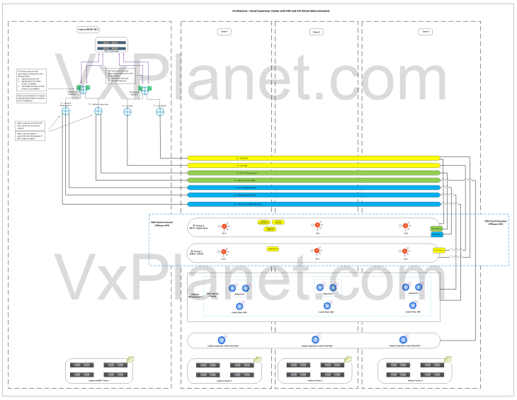
As discussed in Part 1 – Architecture and Topologies, below is the network architecture of a vSphere zonal supervisor deployed across three vSphere zones with AVI availability zones.
Below is a recap of what we discussed in Part 1:
- This architecture has three vSphere clusters each mapped as a vSphere zone. Each vSphere zone is a failure domain. Maximum of three zones are currently supported, and all the three zones / vSphere clusters become one supervisor.
- The three vSphere zones are configured on the same NSX overlay transport zone.
- Supervisor control plane VMs and TKG service cluster VMs (control plane and worker-node-pools) are distributed across the vSphere zones for high availability.
- The edge cluster for the T0 gateway will be deployed on a shared vSphere management – edge cluster or on a dedicated vSphere edge cluster.
- A dedicated SE Group will be created for the vSphere supervisor. The service engines within the SE group will be deployed across the zones with zone awareness (available from AVI 31.1.1 onwards)
- Optionally, another dedicated SE Group per vSphere supervisor can be used to host the system DNS for L7 Ingress / GSLB / AMKO use cases.
Note: To support this topology, the maximum latency between the availability zones should not exceed 100ms.
Current Environment Walkthrough
vSphere walkthrough
I managed to scale out my homelab again with an additional vSphere cluster to make room for this deployment. The lab is currently squeezed to its maximum, but I was able to successfully complete the deployment and capture all the necessary information needed for this article.
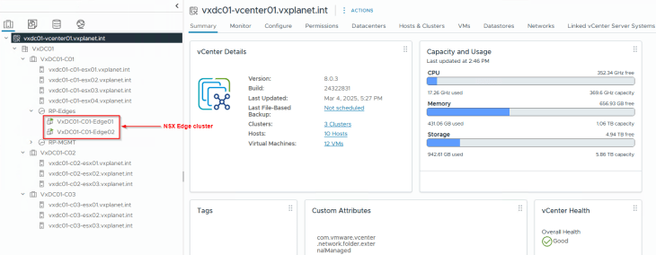
Now we have three vSphere clusters, each mapped as a vSphere zone.
- VxDC01-C01 (Cluster 1)
- VxDC01-C02 (Cluster 2)
- VxDC01-C03 (Cluster 3)
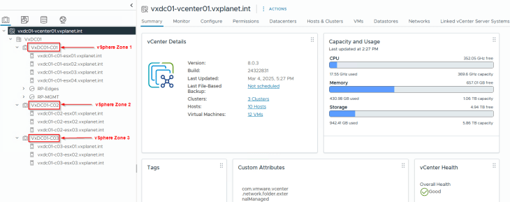
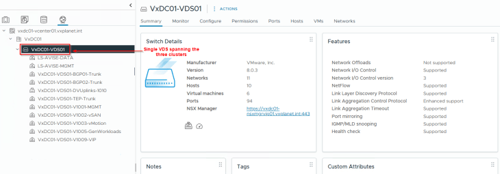
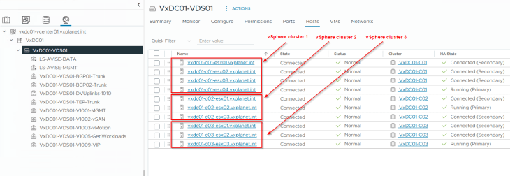
All the vSphere clusters are on a single vCenter VDS. This is currently a requirement.
All the other pre-requisites for supervisor activation (including AVI onboarding workflow) are in place. Please check out Part 2 and Part 3 for more details.
NSX walkthrough
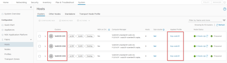
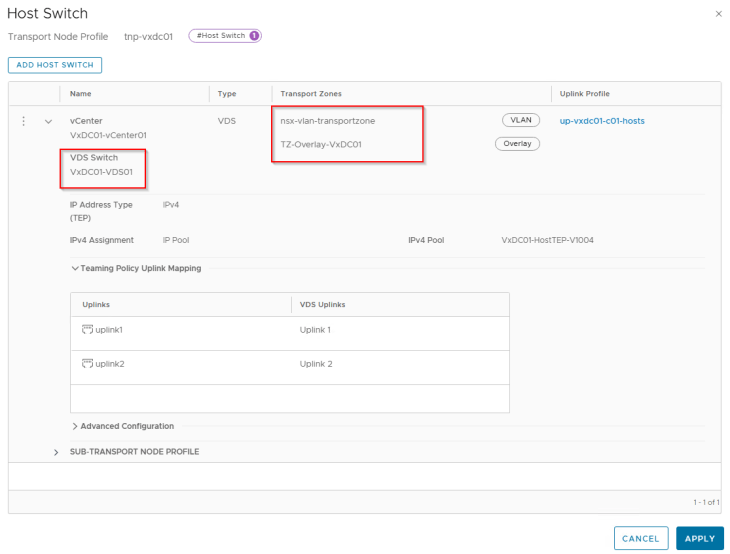
All the vSphere clusters VxDC01-C01, VxDC01-C02 and VxDC01-C03 are prepared for the same NSX overlay transport zone using a transport node profile.
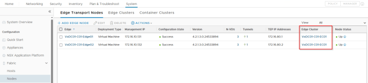
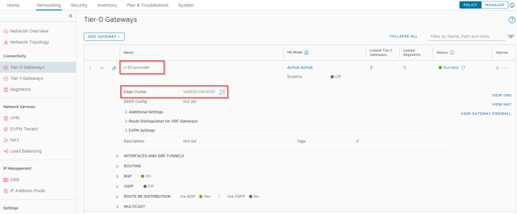
We have an edge cluster prepared on the same NSX overlay transport zone as the vSphere clusters, and hosted on the first vSphere cluster (unlike mentioned in the architecture. This is because I don’t have capacity left in the lab to host a management vSphere cluster).
We have a provider T0 gateway hosted on this edge cluster. Again, due to limited resources in my home lab, the T0 gateway for the supervisor will also handle the management traffic for the AVI SEs and System DNS instead of a dedicated management T0 gateway unlike described in the architecture.
The necessary T0 configurations including BGP peering, route redistribution, route aggregation etc are already in place. Please check out the previous articles to learn more on this configuration.
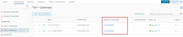
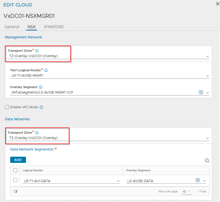
We have two segments created – one for AVI SE management traffic and the other for AVI System DNS traffic, each attached to their respective T1 gateways. The necessary segment and T1 configuration including DHCP, route advertisement etc are already in place.

AVI walkthrough
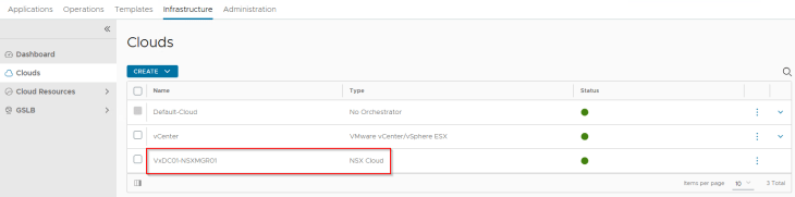
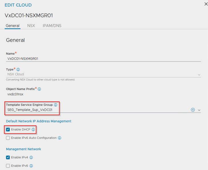
We have a single NSX cloud connector for the NSX overlay transport zone where the vSphere clusters are prepared with.
We have added a template service engine group under the cloud connector which will be cloned for use with vSphere supervisor.
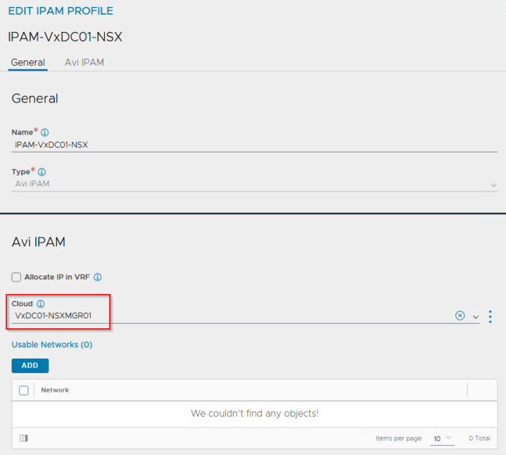
We have IPAM and DNS profiles attached to the cloud connector. This placeholder IPAM profile doesn’t have any networks added, and will be dynamically updated as and when the vSphere supervisors and vSphere namespaces are configured.
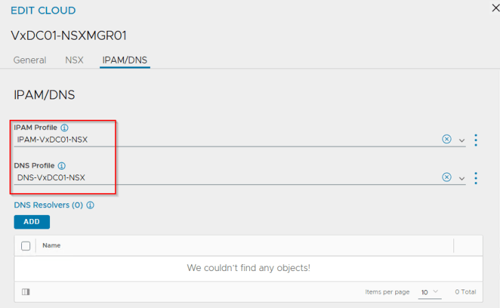
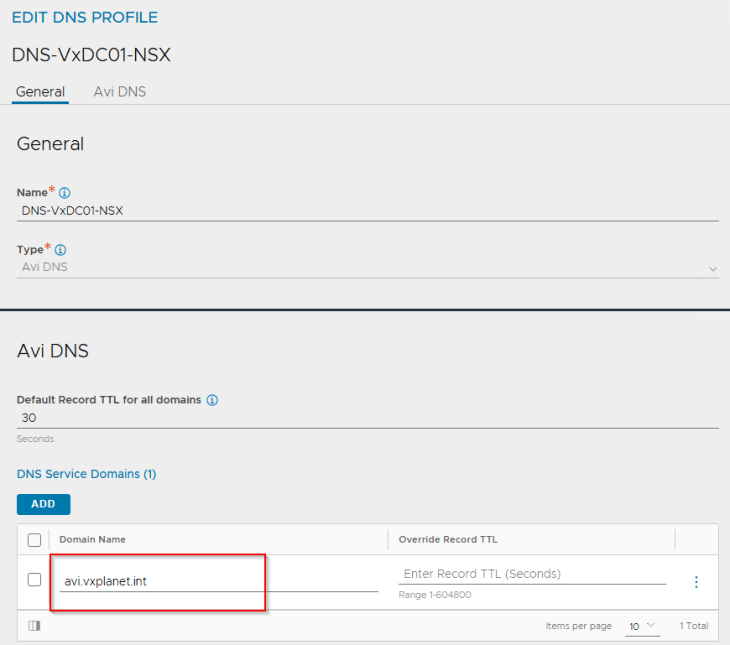
A DNS sub-domain is configured under the cloud connector, that will be used by L7 Ingress on the TKG service clusters. Additional sub-domains can be added later, if needed.
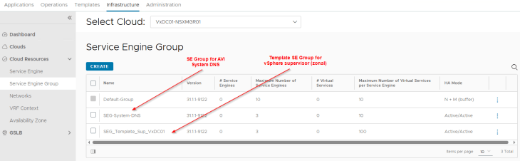
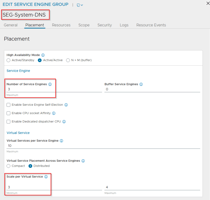
We have two SE Groups configured under the cloud connector – one for the system DNS virtual service and the other is a template SE Group used under the cloud connector. Currently, placement settings are not configured, we will do this in the next section.
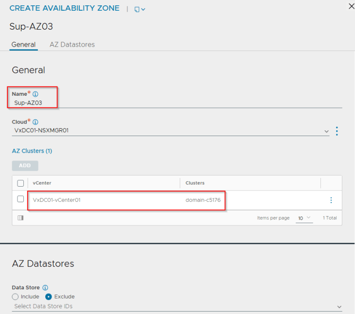
Configuring AVI SE Availability zones
The concept of availability zones for AVI service engine deployment has been introduced in version 31.1.1 to support zone based deployments. Currently availability zones map to vSphere clusters. With availability zones, the service engines will be deployed in round robin across vSphere clusters, and as discussed earlier, it’s important that vSphere clusters are prepared with the same vCenter VDS and NSX transport zones. This is because availability zone settings are specified under the Service engine group and all SEs deployed under an SE Group inherits the same network settings.
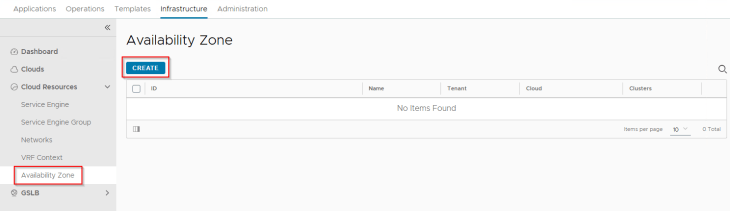
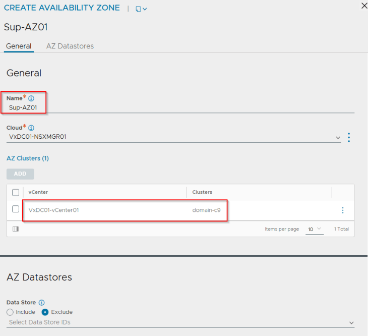
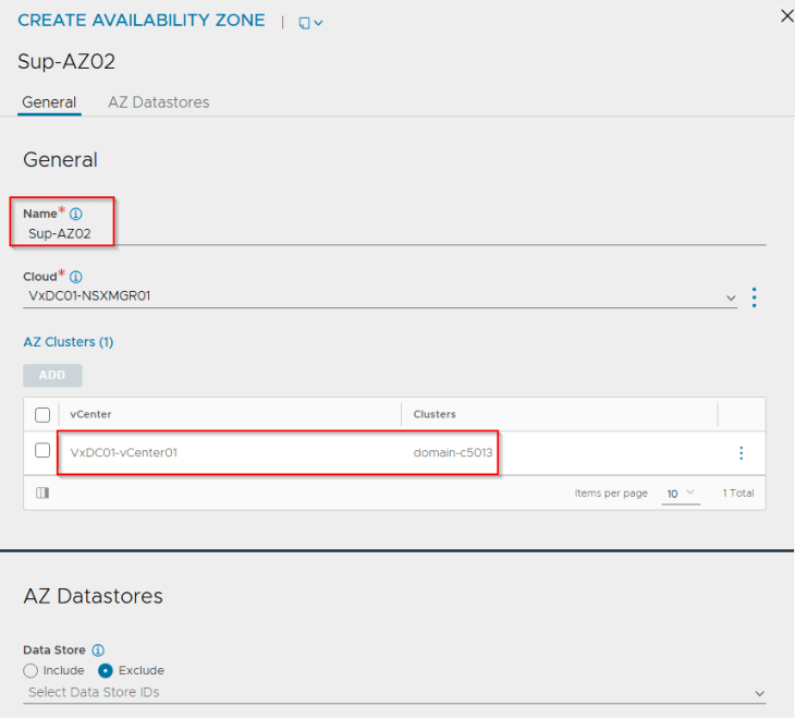
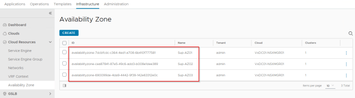
We will create three availability zones – each zone mapping to a vSphere cluster.
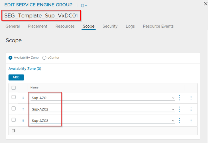
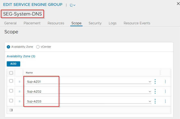
Now. Let’s edit the SE Groups and change the placement method to availability zones.
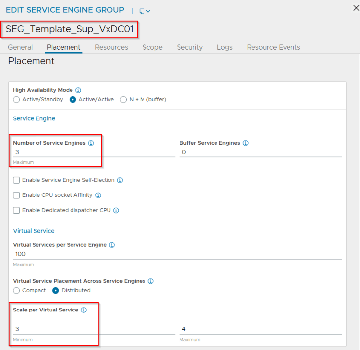
The HA mode for the SE Group can be any of the following:
- N+M mode with 2 SEs and 1 buffer: This allows the virtual services to be placed across two SEs with a buffer (hot-spare) SE that can take over in case of an AZ failure. The SEs will be distributed across the three zones.
- A/A mode with 2 or 3 SEs: This allows the virtual services to be placed across 2 or 3 SEs depending on the VS scale factor. The SEs will be distributed across the three zones.
For this article, we will go with an A/A mode with a VS scale factor of 3. However, N+M mode with 2 SEs and 1 buffer is also a good choice.
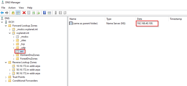
Creating the system DNS virtual service
As in the previous articles, we will now create a system DNS virtual service and allow the AVI service engines to be deployed across the vSphere zones.
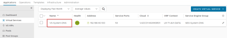
and a delegation for the DNS subdomain on the upstream DNS servers to point to the AVI DNS virtual service.
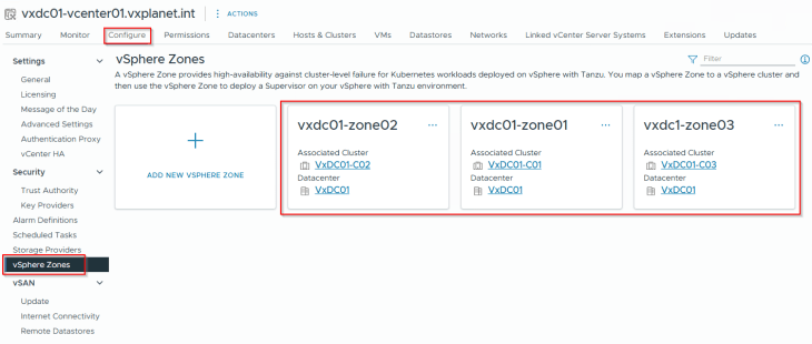
Creating vSphere Zones
We will now map the vSphere clusters to vSphere zones that will be used for the supervisor activation workflow.
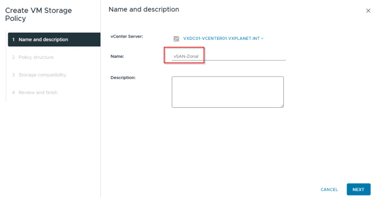
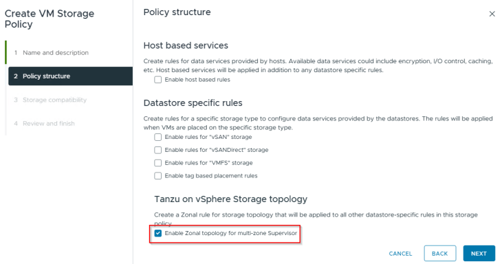
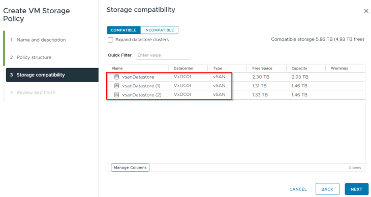
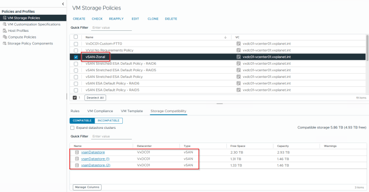
Creating zonal topology-aware storage policy
The default storage policy that we used in the previous articles cannot be used for zonal supervisor deployment. We need to create a new policy that is zone aware, which is just to make sure that we have a common storage policy across all the zones.
We should see the vSAN datastores from each of the three vSphere clusters.
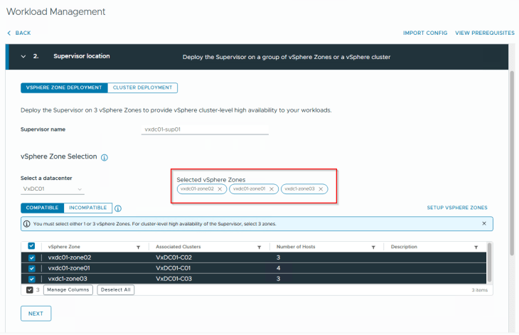
Activating zonal supervisor
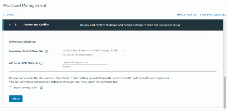
We are now ready to activate the zonal supervisor.
We will launch Workload management, and next to the Cluster deployment tab (which we have been working on all the previous chapters), we also have a Zone Deployment tab where we will select all the three vSphere zones that we created previously.
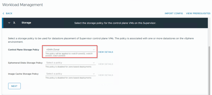
Zonal supervisor doesn’t support vSphere pods, so we will only choose a control plane storage policy. We will select the zonal policy that was created earlier.
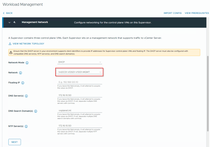
The management network for the vSphere supervisor is a single vCenter DVPG that should available across all the vSphere clusters (zones). Remember, we prepared all the vSphere clusters on the same VDS, and this is the reason why we did that.
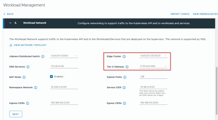
We will select the edge cluster “VxDC01-C01-EC01” and the T0 gateway “lr-t0-provider” that is meant for this supervisor.
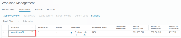
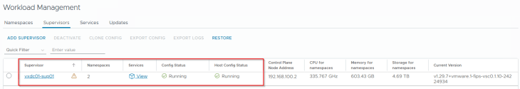
Success!!! vSphere zonal supervisor activation has succeeded.
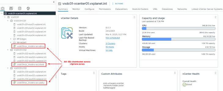
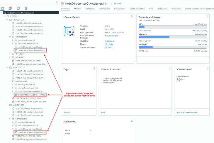
We see that the supervisor control plane VMs are deployed across the three vSphere zones.
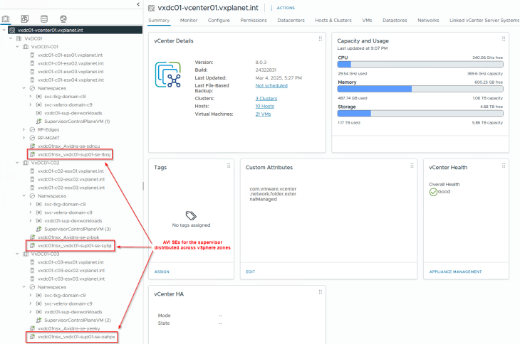
And the same goes for AVI service engines too.
Reviewing NSX objects
Now let’s review the NSX objects that are created by the workflow.
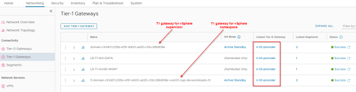
Similar to the previous chapters, dedicated T1 gateways are created for vSphere supervisor and vSphere namespaces. These T1 gateways upstream to their respective T0 gateways, as shown below:
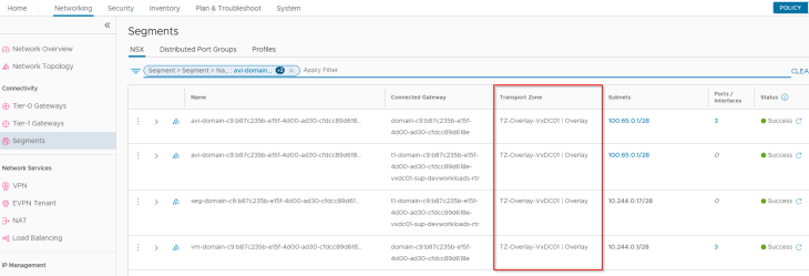
The supervisor workload segments, namespace segments, TKG service cluster segments and the AVI data segments for zonal supervisor are created on the same overlay transport zone, that spans across all the vSphere clusters.
Reviewing AVI objects
Now let’s review the AVI objects that are created by the workflow.
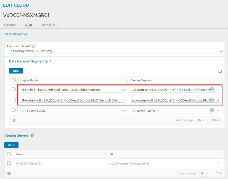
The T1 gateways and the respective AVI data segments are added by the workflow as data networks to the NSX cloud connector.
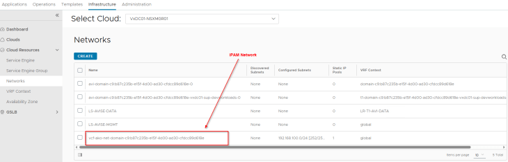
We have an IPAM network created under the NSX cloud connector that maps to the Ingress CIDR defined in the zonal supervisor activation workflow.
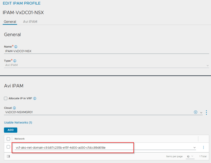
The IPAM network is added dynamically to the IPAM profile for the NSX cloud connector.
We also see that an SE Group is created for the supervisor that is cloned from the respective template SE group, inherited the correct SE placement settings and that the SEs are deployed across vSphere zones.
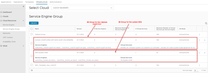
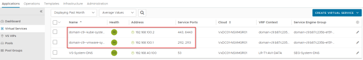
and finally, we have the supervisor control plane VIPs created successfully in AVI
Template SE Group cloning issues
If you face a scenario where the supervisor activation workflow fails to clone the template SE Group that is added to the NSX cloud connector, it’s most likely that the deployment would fail. I have faced this issue multiple times in the lab, however I don’t see any KBs documented for this so far, so I assume it’s just in my lab.
What I observed was that the workflow failed to clone the template SE Group when the AZ placement settings are configured, and if I change to vCenter placement settings, the cloning was successful, as below:
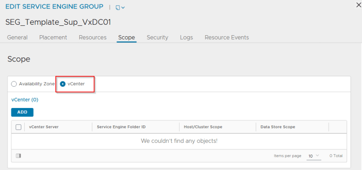
So, here is what I did to get past this issue:
- Use a template SE Group in the NSX cloud connector with placement scope set as vCenter instead of Availability zones
- Run the supervisor activation workflow and wait for it to succeed.
- The service engines will be deployed without zone awareness and could even land on the same vSphere cluster
- Disable the supervisor control plane VIPs in AVI
- Delete the service engines that are deployed, manually from the AVI controller
- Edit the new cloned SE Group and change the placement settings to Availability zones.
- Enable the supervisor control plane VIPs in AVI
- This will allow new service engines to be deployed with zone awareness in vCenter
I don’t think you will hit this issue, but just for guidance.
TKG service clusters and zone awareness
- When a TKG service cluster is deployed, the control plane nodes will be deployed across the three vSphere zones.
- TKG service cluster worker nodes can be deployed across vSphere zones by defining a “failureDomain” for each node pool. Each “failureDomain” maps to a vSphere Zone, and hence each node-pool will be deployed to a specific vSphere zone, as shown in the below spec:
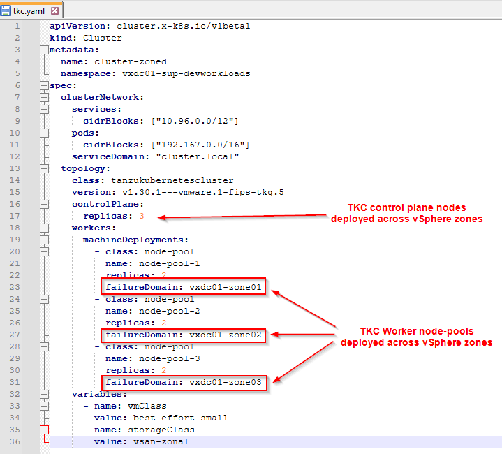
Unfortunately, I don’t have lab capacity to deploy the TKG service cluster, but I hope the concept makes sense.
It’s time to wrap up!!! This has been a lengthy blog series with two months of effort, and the intention behind the series was to provide the necessary guidance to accelerate learning and adoption. Thanks to all the readers who were following along. With VCF 9 around the corner, let’s wait to see what enhancements we see in this space, stay tuned!!!

Continue reading? Here are the other parts of this series:
Part 1: Architecture and Topologies
https://vxplanet.com/2025/04/16/vsphere-supervisor-networking-with-nsx-and-avi-part-1-architecture-and-topologies/
Part 2: Environment Build and Walkthrough
https://vxplanet.com/2025/04/17/vsphere-supervisor-networking-with-nsx-and-avi-part-2-environment-build-and-walkthrough/
Part 3: AVI onboarding and Supervisor activation
https://vxplanet.com/2025/04/24/vsphere-supervisor-networking-with-nsx-and-avi-part-3-avi-onboarding-and-supervisor-activation/
Part 4: vSphere namespace with network inheritance
https://vxplanet.com/2025/05/15/vsphere-supervisor-networking-with-nsx-and-avi-part-4-vsphere-namespace-with-network-inheritance/
Part 5: vSphere namespace with custom Ingress and Egress network
https://vxplanet.com/2025/05/16/vsphere-supervisor-networking-with-nsx-and-avi-part-5-vsphere-namespace-with-custom-ingress-and-egress-network/
Part 6: vSphere namespace with dedicated T0 gateways
https://vxplanet.com/2025/05/16/vsphere-supervisor-networking-with-nsx-and-avi-part-6-vsphere-namespace-with-dedicated-t0-gateway/
Part 7: vSphere namespace with dedicated VRF gateways
https://vxplanet.com/2025/05/20/vsphere-supervisor-networking-with-nsx-and-avi-part-7-vsphere-namespace-with-dedicated-t0-vrf-gateway/
Part 8: Multiple supervisors on shared NSX transport zone
https://vxplanet.com/2025/06/08/vsphere-supervisor-networking-with-nsx-and-avi-part-8-multiple-supervisors-on-shared-nsx-transport-zone/
Part 9: Multiple supervisors on dedicated NSX transport zones
https://vxplanet.com/2025/06/08/vsphere-supervisor-networking-with-nsx-and-avi-part-9-multiple-supervisors-on-dedicated-nsx-transport-zones/


