
Starting vSphere 8.0U2 , vSphere Supervisor added support for NSX integration with VMware AVI load balancer. This integration is extremely important for two reasons:
- VMware by Broadcom has announced deprecation of the NSX native load balancer and the recommendation is to use AVI load balancer moving forward. Native load balancer will be supported only for specific use cases.
- A single load balancing platform to manage all K8S L4 and L7 ingress VIPs with advanced load balancing features including WAF and GSLB.
This integration requires the below minimum versions of NSX and AVI:
- NSX version 4.1.1 or later
- AVI version 22.1.4 or later
In this 11-part blog series, we will do a comprehensive deep-dive on the networking and load balancing architecture for vSphere supervisor covering the different topologies for supervisor clusters, vSphere namespaces with custom network topologies, multiple supervisor clusters and zonal supervisors, here is the breakdown:
Part 1: Architecture and Topologies
Part 2: Current Environment walkthrough
Part 3: Activating vSphere Supervisor with NSX and AVI integration
Part 4: vSphere namespace with network inheritance
Part 5: vSphere namespace with custom Ingress and Egress network
Part 6: vSphere namespace with dedicated T0 gateways
Part 7: vSphere namespace with dedicated VRF gateways
Part 8: Multiple supervisors on shared NSX transport zone
Part 9: Multiple supervisors on dedicated NSX transport zone
Part 10: Multiple supervisors on dedicated NSX/AVI instances with multi-NSX feature
Part 11: Three-zone supervisor
Before we proceed, lets discuss some considerations that we need to be aware of with this integration:
Considerations for Supervisor Networking with NSX and AVI
- NCP provisions all the networking objects in the default space in NSX manager, and we don’t have support for NSX projects (multi-tenancy)
- All T1 gateways provisioned by NCP as part of the workflow are stateful A/S. There is no support for stateful A/A gateways. If the T0 gateway (Provider) is provisioned as stateful A/A, then a dedicated edge cluster need to be available to host the T1 gateways created by NCP.
- One T1 gateway will be provisioned per vSphere namespace. Any TKG service clusters created in the vSphere namespace will attach to a dedicated segment under the T1 gateway
- One SNAT IP is allocated to the vSphere namespace that will be used by all vSphere pods and TKG service clusters in the namespace.
- There is no SNAT for east – west communication between vSphere namespaces.
- In most cases, vSphere namespaces will be created with NAT enabled, but it’s possible to have vSphere namespaces with routable networks. Depending on use cases, it might be necessary to configure additional networking (like inter-T0 transit links, VRF route leaking etc) to allow vSphere namespaces communicate with the supervisor. We will cover these scenarios in the subsequent chapters.
- The default CNI of the TKG service clusters will be Antrea. By integrating Antrea with NSX manager, we have a single pane of management (NSX manager) for Antrea security policies (DFW / IDPS).
- AKO in the supervisor cluster provisions K8S services of type load balancer in the default “admin” tenant in AVI. Currently there is no option to steer the VIPs to a dedicated AVI tenant.
- AKO can be used as the Ingress controller for the TKG service clusters. Ingress services (L7) can be steered to any specific AVI tenant, this is defined in the config map object while deploying AKO.
- The AVI cloud connector used for the integration will be an “NSX cloud connector”. An overlay transport zone in NSX maps as an NSX cloud connector in AVI and there can be only one NSX cloud connector per overlay transport zone. During the supervisor enablement phase, the NSX cloud connector will be chosen automatically based on the overlay transport zone that the supervisor vSphere cluster is configured on.
- One AVI SE Group will be used per supervisor cluster. Depending on the HA model and the VS scale factor, enough AVI service engines need to be available in the SE group to cater for the increasing number of vSphere namespaces. For example, one vSphere namespace consumes one interface of the AVI service engine, and as such, in an SE Group with 2 SEs and with a VS scale factor of 2 we could support up to 10 vSphere namespaces. Additional namespaces require more SEs to be spun up in the SE Group.
- For each SNAT IP and VIP that is provisioned under a namespace , a /32 host route is advertised by the T0 gateway out to the physical fabrics. In most cases, route aggregation for the Ingress and Egress networks will be applied manually at the T0 gateway.
- If AVI service engines are deployed in A/A HA mode, they need to be added to DFW exclusion list to prevent asymmetric flows from getting blocked by the stateful NSX DFW.
Okay, now let’s discuss the architecture and topologies, subsequent chapters in this blog series cover each of the topologies in more detail:
vSphere Supervisor Architecture with NSX and AVI
Below is the network architecture for a standard vSphere supervisor with NSX and AVI:
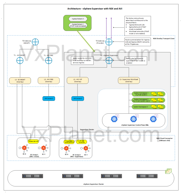
- A dedicated T1 gateway (A/S) is created for the vSphere supervisor
- This T1 gateway is hosted on the edge cluster and up streamed to the T0 gateway that was specified during the supervisor activation workflow.
- A dedicated segment (workload) is created under the T1 gateway for the vSphere supervisor where the supervisor control plane VMs and vSphere pods will attach to. Based on the configuration, this network can be routable or behind NAT.
- A dedicated non-routable segment (AVI data) is created under the T1 gateway where the AVI SE’s data interface attaches to. This segment is used to reach the VIPs for the vSphere supervisor.
- If NAT mode is enabled for the vSphere supervisor, one SNAT IP will be used for all outbound traffic from the supervisor T1.
- Static routes for the VIPs will be programmed on the T1 gateway by the NSX cloud connector with next-hop pointing to the AVI SE’s data interfaces.
- Route summarization for the Ingress and Egress CIDR will be done manually on the T0 (Provider) gateway.
- One SE Group (shared) will be used for the vSphere supervisor and all the vSphere namespaces.
- SEs work in single arm mode.
- vSphere supervisor and namespaces will be mapped as dedicated VRF contexts in AVI, thereby ensuring network isolation of the VIPs.
- The IPAM profile attached to the NSX cloud connector will be dynamically updated with the Ingress network.
- AVI SE management network can be on a dedicated management data path, with a dedicated management T0 gateway peering with the management physical fabrics. However, this is optional.
- Optionally, a dedicated SE Group will be used to host the AVI system DNS service. This is used for the AVI DNS profile to support Ingress services of TKG service clusters and also for AMKO / GSLB.
- The below networks are advertised northbound from the T0 gateway to the physical fabrics:
- Ingress network (used in LB)
- Egress network, if NAT mode is enabled (used in SNAT rules)
- Workload network (if NAT mode is not enabled)
Architecture – vSphere Namespace inheriting supervisor cluster network settings
Below is the network architecture for a vSphere namespace inheriting network settings from the supervisor cluster:
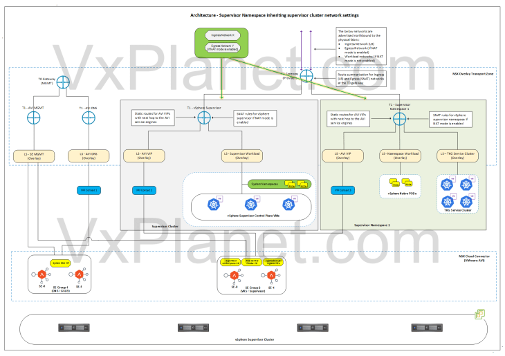
- A dedicated T1 gateway (A/S) is created for the vSphere namespace
- This T1 gateway is hosted on the same edge cluster and up streamed to the same T0 gateway as the supervisor.
- A dedicated segment (namespace network) is created under the T1 gateway for the vSphere namespace where the vSphere pods will attach to. Based on the configuration, this network can be routable or behind NAT.
- A dedicated segment (TKG cluster network) is created under the T1 gateway for each TKG service cluster that is deployed in the vSphere namespace. Based on the configuration, this network can be routable or behind NAT.
- A dedicated non-routable segment (AVI data) is created under the T1 gateway where the AVI SE’s data interface attaches to. This segment is used to reach the VIPs under the vSphere namespace.
- If NAT mode is enabled for the vSphere namespace, one SNAT IP will be used for all outbound traffic from the namespace T1. East- west between the namespaces and to supervisor will be no-SNAT.
- Communication between the namespaces and supervisor happens at the T0 gateway (without NAT).
- Static routes for the VIPs will be programmed on the T1 gateway by the NSX cloud connector with next-hop pointing to the AVI SE’s data interfaces.
- Route summarization for the Ingress and Egress CIDR will be done manually on the T0 (Provider) gateway.
- The same SE Group of the vSphere supervisor will be used by the vSphere namespaces.
- SEs work in single arm mode.
- Each vSphere namespace will be mapped as dedicated VRF contexts in AVI, thereby ensuring network isolation of the VIPs.
- The Ingress network defined in the IPAM profile for the supervisor will be used for the vSphere namespace.
- One AVI SE data interface will be consumed for each vSphere namespace. Depending on the HA mode and VS scale factor, enough SEs need to be available in the SE Group to cater for the increasing number of vSphere namespaces. For example, in an SE Group with 2 SEs and with a VS scale factor of 2 we could support up to 10 vSphere namespaces. Additional namespaces require more SEs to be spun up in the SE Group
- Any Ingress created on the TKG service clusters will leverage the System DNS profile attached to the NSX cloud connector. Managing the DNS profile and subdomain mapping will be a manual task.
- The below networks are advertised northbound from the T0 gateway to the physical fabrics:
- Ingress network (used in LB)
- Egress network, if NAT mode is enabled (used in SNAT rules)
- Supervisor workload network (if NAT mode is not enabled)
- Namespace network (if NAT mode is not enabled)
- TKG cluster network (if NAT mode is not enabled)
Architecture – vSphere Namespace with custom Ingress and Egress Networks
Below is the network architecture for a vSphere namespace with a custom Ingress and Egress network:
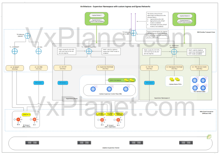
The architecture is same as previously but with the below changes:
- A custom Namespace network, Ingress network and Egress network will be used for the vSphere namespace.
- The vSphere namespace network will be different than the one used for supervisor. TKG cluster network will be carved out from this new namespace network. Based on the configuration, this network can be routable or behind NAT.
- If NAT mode is enabled for the vSphere namespace, one SNAT IP will be used for all outbound traffic from the namespace T1. This SNAT IP comes from the new Egress network defined for the namespace. East- west between the namespaces and to supervisor will be no-SNAT
- Communication between the namespaces and supervisor happens at the T0 gateway (without NAT).
- A new VIP network will be added to the IPAM profile of the cloud connector. This VIP network comes from the new Ingress network defined for the namespace.
- Route summarization for the custom Ingress and Egress CIDR for the vSphere namespace will be done manually on the T0 (Provider) gateway.
- The below networks are advertised northbound from the T0 gateway to the physical fabrics:
- Ingress network of supervisor and namespaces inheriting network settings.
- Egress network of supervisor and namespaces inheriting network settings, if NAT mode is enabled
- Supervisor workload network (if NAT mode is not enabled)
- Namespace network (if NAT mode is not enabled)
- TKG cluster network (if NAT mode is not enabled)
- Custom Ingress and Egress network of vSphere namespaces.
Architecture – vSphere Namespace with dedicated T0 gateway (NAT mode disabled)
Below is the network architecture for a vSphere namespace with a dedicated T0 gateway and with NAT mode disabled. vSphere namespaces with dedicated T0 / VRF gateway is used to cater for specific requirements like application publishing, application traffic routed through a different firewall, IDPS / TLS inspection or any other kind of treatment.
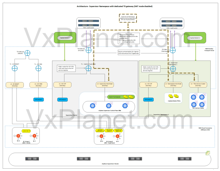
In this architecture, it’s assumed that both the supervisor and namespace have NAT mode disabled.
- A custom T0 gateway, namespace network and Ingress network will be used for the vSphere namespace. Egress network is not applicable here as NAT mode is disabled.
- A dedicated T1 gateway (A/S) is created for the vSphere namespace
- This T1 gateway is up streamed to the custom T0 gateway for the namespace and hosted on the same edge cluster as the custom T0 gateway for the namespace.
- The vSphere namespace network will be different than the one used for supervisor. TKG cluster network will be carved out from this new namespace network.
- A dedicated non-routable segment (AVI data) is created under the T1 gateway where the AVI SE’s data interface attaches to. This segment is used to reach the VIPs under the vSphere namespace.
- Because NAT mode is not used in supervisor and namespaces, supervisor workload network, namespace network and TKG cluster networks are advertised northbound from the respective T0 gateways to the physical fabrics.
- Static routes for the VIPs will be programmed on the T1 gateway by the NSX cloud connector with next-hop pointing to the AVI SE’s data interfaces.
- A new VIP network will be added to the IPAM profile of the cloud connector. This VIP network comes from the new Ingress network defined for the namespace.
- Route summarization for the custom Ingress CIDR for the vSphere namespace will be done manually on the T0 gateway for the namespace.
- The same SE Group of the vSphere supervisor will be used by the vSphere namespaces.
- The below networks are advertised northbound from the T0 gateway of the namespace to the physical fabrics:
- Ingress network (used in LB)
- Namespace network
- TKG cluster network
- As the supervisor workload network and namespace networks are advertised to the physical fabrics (TOR switches), routing between them happens without SNAT outside of the T0 gateway.
Architecture – vSphere Namespace with dedicated T0 gateway (NAT mode enabled)
Below is the network architecture for a vSphere namespace with a dedicated T0 gateway and with NAT mode enabled. In this architecture, it’s assumed that the supervisor have NAT mode either enabled or disabled.
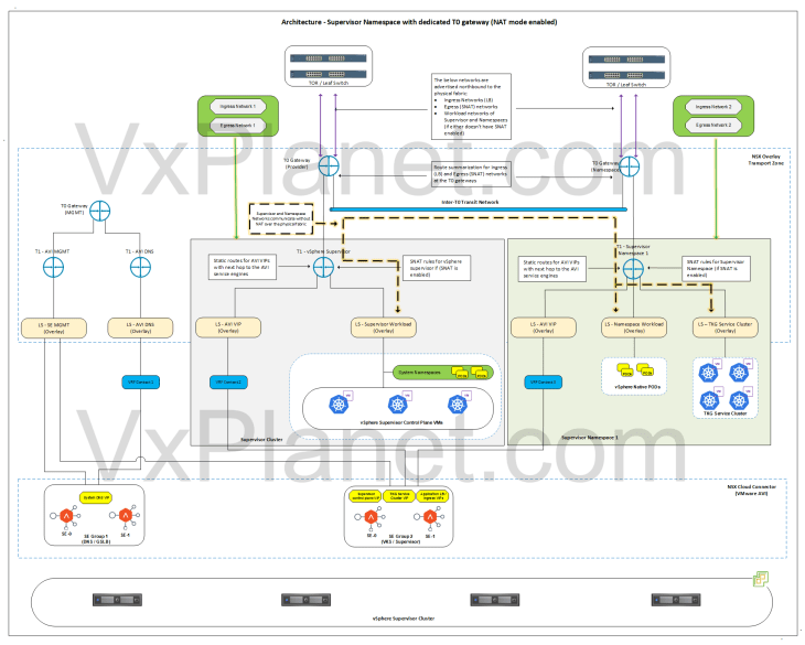
This architecture is same as previously with the no-NAT mode but with the below changes:
- A custom T0 gateway, namespace network, egress network and Ingress network will be used for the vSphere namespace.
- Because NAT mode is enabled for the vSphere namespace, one SNAT IP will be used for all outbound traffic from the namespace T1. This SNAT IP comes from the new Egress network defined for the namespace. East- west between the namespaces and to supervisor will be no-SNAT.
- The below networks are advertised northbound from the T0 gateway of the namespace to the physical fabrics:
- Ingress network (used in LB)
- Egress network (used in SNAT rules)
- Because the namespace networks are not advertised by the T0 gateway to the physical fabrics, we need additional routing configuration to establish connectivity between the supervisor and namespace networks. We have multiple approaches:
- Static routing on the physical fabrics for the supervisor and namespace networks – This might not be practical in many scenarios
- GRE tunnels between the T0 gateways – This adds complexities and requires loopback interfaces to be advertised to the physical fabrics
- Inter-VRF overlay transit link – Because the provider T0 and namespace T0 are in same NSX overlay transport zone, this will be a simpler and better approach.
- In the above architecture, we have an inter-T0 transit link established between the provider and namespace T0 gateways with static routing created for the supervisor and namespace networks. This allows supervisor and namespace networks to communicate with each other without NAT.
Architecture – vSphere Namespace with dedicated T0 VRF gateway (NAT mode disabled)
Below is the network architecture for a vSphere namespace with a dedicated T0 VRF gateway and with NAT mode disabled.
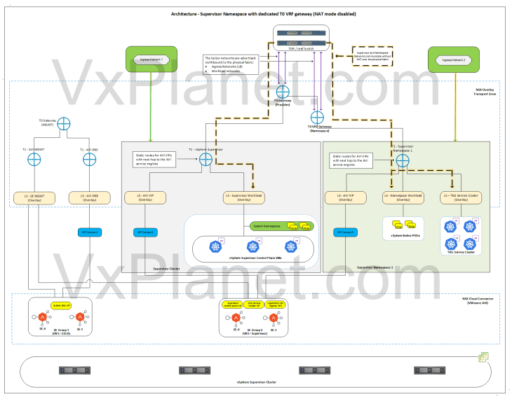
In this architecture, it’s assumed that both the supervisor and vSphere namespace have NAT mode disabled.
- A custom T0 VRF gateway, namespace network and Ingress network will be used for the vSphere namespace. Egress network is not applicable here as NAT mode is disabled.
- A dedicated T1 gateway (A/S) is created for the vSphere namespace
- This T1 gateway is up streamed to the T0 VRF gateway for the namespace and hosted on the same edge cluster as the parent T0 gateway.
- The vSphere namespace network will be different than the one used for supervisor. TKG cluster network will be carved out from this new namespace network.
- A dedicated non-routable segment (AVI data) is created under the T1 gateway where the AVI SE’s data interface attaches to. This segment is used to reach the VIPs under the vSphere namespace.
- Because NAT mode is not used in supervisor and namespaces, supervisor workload network, namespace network and TKG cluster networks are advertised northbound from their respective T0 and VRF gateways to the physical fabrics.
- Static routes for the VIPs will be programmed on the T1 gateway by the NSX cloud connector with next-hop pointing to the AVI SE’s data interfaces.
- A new VIP network will be added to the IPAM profile of the cloud connector. This VIP network comes from the new Ingress network defined for the namespace.
- Route summarization for the custom Ingress CIDR for the vSphere namespace will be done manually on the T0 VRF gateway for the namespace.
- The same SE Group of the vSphere supervisor will be used by the vSphere namespaces.
- The below networks are advertised northbound from the T0 gateway of the namespace to the physical fabrics:
- Ingress network (used in LB)
- Namespace network
- TKG cluster network
- As the supervisor workload network and namespace networks are advertised to the physical fabrics (TOR switches), routing between them happens without SNAT outside of the T0 gateway.
Architecture – vSphere Namespace with dedicated T0 VRF gateway (NAT mode enabled)
Below is the network architecture for a vSphere namespace with a dedicated T0 VRF gateway and with NAT mode enabled. In this architecture, it’s assumed that supervisor have NAT mode either enabled or disabled.
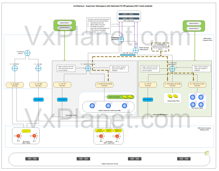
This architecture is same as previously with the no-NAT mode but with the below changes:
- A custom T0 VRF gateway, namespace network, egress network and Ingress network will be used for the vSphere namespace.
- Because NAT mode is enabled for the vSphere namespace, one SNAT IP will be used for all outbound traffic from the namespace T1. This SNAT IP comes from the new Egress network defined for the namespace. East- west between the namespaces and to supervisor will be no-SNAT.
- The below networks are advertised northbound from the T0 VRF gateway of the namespace to the physical fabrics:
- Ingress network (used in LB)
- Egress network (used in SNAT rules)
- Because the namespace networks are not advertised by the T0 VRF gateway to the physical fabrics, we need additional routing configuration to establish connectivity between the supervisor (behind T0) and namespace networks (behind VRF gateway). We accomplish this with inter-VRF routing.
- In the above architecture, we have an inter-VRF transit link established between the VRF gateway and supervisor T0 gateway with routing created for the namespace and supervisor networks. This allows supervisor and namespace networks to communicate with each other without NAT.
Architecture – Multiple vSphere Supervisors on shared NSX Transport Zone
Below is the network architecture of two vSphere supervisors on shared NSX overlay transport zone:
- In this architecture with a shared overlay transport zone, there is no network isolation as the segments created for a supervisor are visible and consumable on all the vSphere clusters that are part of this overlay transport zone.
- Depending on the scenarios, the T0 gateway can be either:
- A single shared T0 gateway for multiple supervisors
- A dedicated T0 gateway for each supervisor
- If a shared T0 gateway approach is used, ideally the T0 edge cluster will be placed on a shared management – edge vSphere cluster or on a dedicated edge vSphere cluster
- If a dedicated T0 gateway approach is used, the T0 edge cluster will be co-located with the supervisor vSphere cluster.
- Each supervisor will have dedicated service & pod CIDRs, namespace networks, ingress networks and egress networks
- Because a single NSX overlay transport zone is used, both supervisors will use the same NSX cloud connector in AVI
- Only a single AVI SE management network can be defined in an NSX cloud connector, hence it makes more sense to have a dedicated management T1 and T0 gateway to handle AVI SE management traffic and placed on the vSphere management cluster, as in the above architecture.
- A dedicated SE Group will be used per supervisor.
- Optionally, a dedicated SE Group will be used to host the AVI system DNS service. This is used for the AVI DNS profile to support Ingress services of TKG service clusters. This SE group can be placed on either of the supervisors but attached to the management T0 gateway on the vSphere management cluster.
- All the NSX objects are created in the default space in NSX and all the AVI VIPs are created in the default admin tenant (except Ingress of the TKG service clusters, which can be steered to specific tenants). Hence this architecture doesn’t have management plane isolation for the supervisor objects in NSX and AVI.
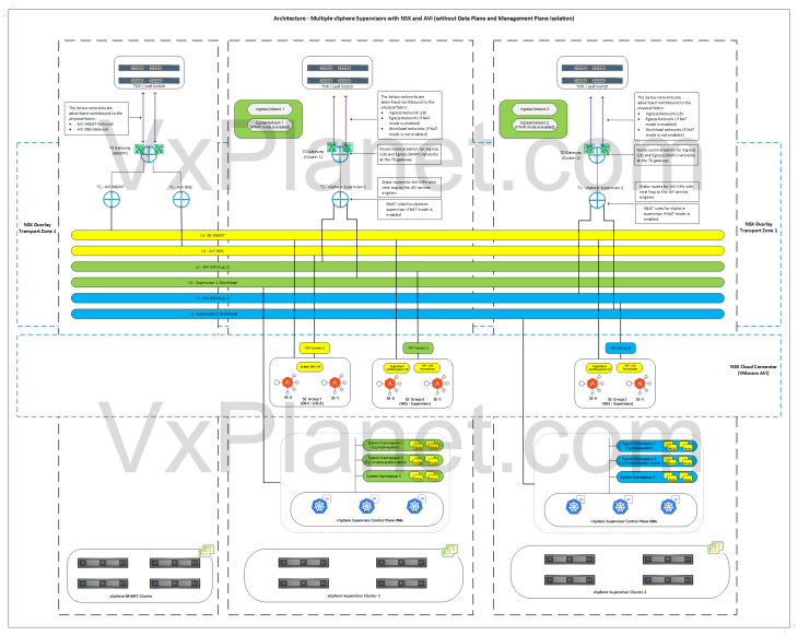
Architecture – Multiple vSphere Supervisors on dedicated NSX Transport Zone
Below is the network architecture of two vSphere supervisors each on a dedicated NSX overlay transport zone:

- In this architecture with dedicated overlay transport zones, each vSphere supervisor cluster is configured on a dedicated NSX overlay transport zone. There is network isolation between the vSphere supervisors as the segments created for one supervisor are visible and consumable only by that specific vSphere supervisor.
- There will be dedicated T0 gateways for each vSphere supervisor.
- The T0 edge cluster of each vSphere supervisor will be co-located on the same vSphere cluster.
- Each supervisor will have dedicated service & pod CIDRs, namespace networks, ingress networks and egress networks
- There is a 1:1 mapping between an NSX overlay transport zone and AVI cloud connector. Hence each supervisor will use separate NSX cloud connectors in AVI.
- Because each supervisor has a dedicated NSX cloud connector in AVI, the AVI SE management network can use the same T0 gateway of the supervisor, as in the above architecture.
- A dedicated SE Group will be used per supervisor, and this SE group belongs to the respective NSX cloud connector.
- Optionally, a dedicated SE Group per vSphere supervisor can be used to host the system DNS for GSLB / AMKO use cases.
- Similar to the architecture on a shared overlay transport zone, all the NSX objects are created in the default space in NSX and all the AVI VIPs are created in the default admin tenant (except Ingress of the TKG service clusters, which can be steered to specific tenants). Hence this architecture also doesn’t have management plane isolation for the supervisor objects in NSX and AVI.
Architecture – Multiple vSphere Supervisors with management plane isolation using Multi-NSX feature
Below is the network architecture of two vSphere supervisors each managed by separate NSX instances using Multi-NSX feature. Each NSX instance has a 1:1 mapping with an AVI instance, hence each supervisor will have a dedicated AVI instance as well.
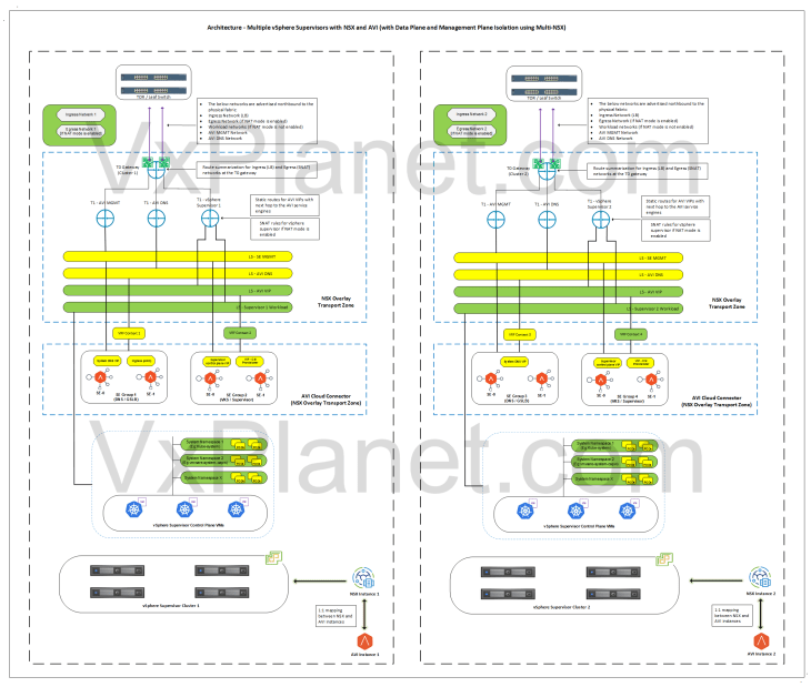
- In this architecture, each vSphere supervisor has a dedicated NSX and AVI instance.
- Each supervisor has complete data plane isolation for the networks that it creates.
- There will be dedicated T0 gateways for each vSphere supervisor.
- The T0 edge cluster of each vSphere supervisor will be co-located on the same vSphere cluster.
- Each supervisor will have dedicated service & pod CIDRs, namespace networks, ingress networks and egress networks
- Each supervisor will use separate NSX cloud connectors, each under it’s respective AVI instance.
- A dedicated SE Group will be used per supervisor, and this SE group belongs to the respective AVI instance.
- Optionally, a dedicated SE Group per vSphere supervisor can be used to host the system DNS for GSLB / AMKO use cases.
- Unlike the previous architectures, NSX and AVI objects are created under their respective NSX and AVI instances. Hence this architecture provides both data plane and management plane isolation for the supervisor objects.
Architecture – Zonal Supervisor with NSX and AVI
Below is the network architecture of a three-zone supervisor with NSX and AVI:
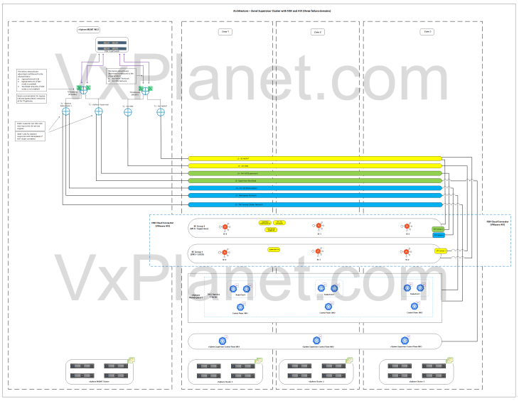
- This architecture has three vSphere clusters each mapped as a vSphere zone. Each vSphere zone is a failure domain
- The three vSphere zones are configured on the same NSX overlay transport zone.
- Supervisor control plane VMs and TKG service cluster VMs (control plane and worker-node-pools) are distributed across the vSphere zones for high availability.
- The edge cluster for the T0 gateway will be deployed on a shared vSphere management – edge cluster or on a dedicated vSphere edge cluster.
- A dedicated SE Group will be created for the vSphere supervisor. The service engines within the SE group will be deployed with zone awareness (available from AVI 31.1.1 onwards)
- Optionally, another dedicated SE Group per vSphere supervisor can be used to host the system DNS for GSLB / AMKO use cases.
Okay, it’s time to conclude this article. This has been a lengthier one, but I am sure this gave you valuable insights on the vSphere supervisor architecture and topologies with NSX and AVI. In the subsequent chapters, we will cover the implementation details and configuration of each architecture in more detail.
Stay tuned!!!
Thanks for reading and don’t forget to offer me a drink if you found this insightful.


![My Community Project – VMware AVI Virtual Service Migrator v1.4 [Version Release Update]](https://vmwarecloud.com.au/wp-content/webp-express/webp-images/uploads/2025/03/my-community-project-vmware-avi-virtual-service-migrator-v1-4-version-release-update.png.webp)