
Welcome back!!! Now that we activated vSphere supervisor in the previous article, let’s do few chapters (Part 4, 5, 6 & 7) on the different topologies of vSphere namespaces starting with vSphere namespaces inheriting network settings from the vSphere supervisor. If you missed the previous article on AVI onboarding and vSphere supervisor activation, please check it out below:
Part 3: AVI onboarding and Supervisor activation
https://vxplanet.com/2025/04/24/vsphere-supervisor-networking-with-nsx-and-avi-part-3-avi-onboarding-and-supervisor-activation/
Let’s get started:
vSphere namespace inheriting network settings from the supervisor
In this vSphere namespace topology, we will inherit the below network settings from the vSphere supervisor:
- T0 / VRF Gateway
- Workload / Namespace CIDR
- Ingress CIDR
- Egress CIDR (if NAT mode is enabled)
- NAT mode
Let’s login to vCenter Workload Management and create a vSphere namespace for the dev workloads, making sure the flag for “Override supervisor network settings” is unchecked.

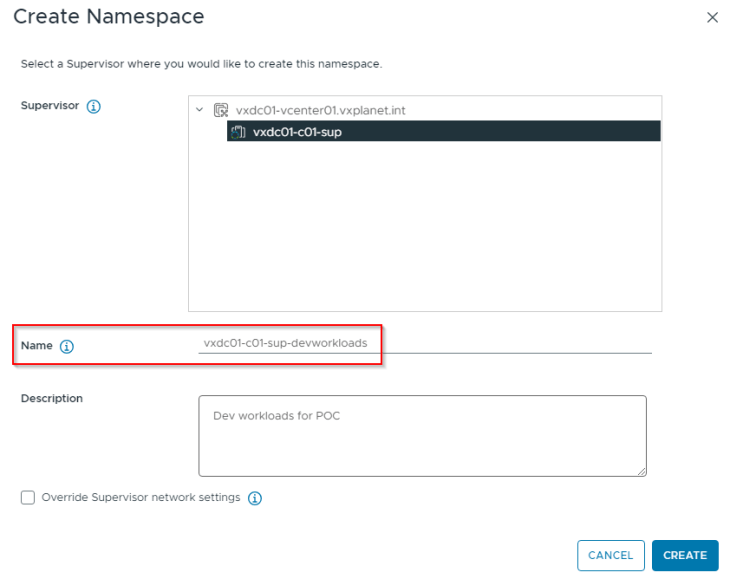
After basic namespace configuration (permissions, storage class, VM Class assignments etc,) we should have the vSphere namespace up and running.

If we review the namespace object, we should see annotations with the details of SNAT IP Pool and address, T1 gateway of namespace, namespace subnet etc. Note that one SNAT IP is used for the entire vSphere namespace that will be shared by all the TKG service clusters deployed within the namespace.

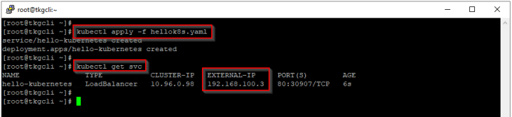
Let’s switch the kubectl context to vSphere namespace and deploy a hellok8s application as vSphere pods.
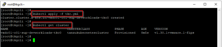
Let’s also deploy a TKG service cluster.
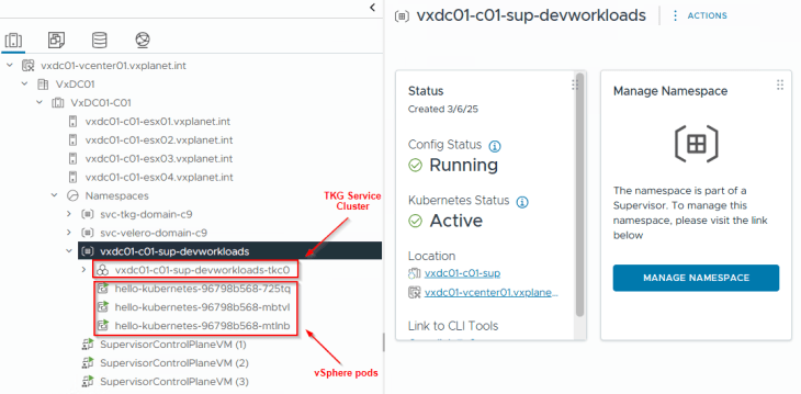
and we should see the vSphere objects for namespace, pods and TKG service cluster in vCenter.
Reviewing NSX objects
Now let’s review the NSX objects that are created by the workflow.
As discussed in Part 1 – Architecture and Topologies, a dedicated T1 gateway is created for the vSphere namespace up streamed to the provider T0 gateway (which is the same T0 gateway used by the vSphere supervisor).

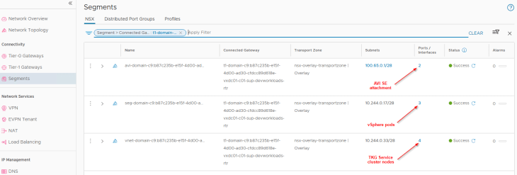
Two default segments are created, both attached to the namespace T1 gateway. We also have additional dedicated segments for each TKG service cluster that is created under the vSphere namespace, all up streamed to the namespace T1 gateway.
- Namespace network : This is where the vSphere pods attach to. This network is carved out from the namespace network specified in the supervisor activation workflow.
- AVI data segment : This is a non-routable subnet on the CGNAT range and has DHCP enabled. This is where the AVI SE data interfaces attach to. A dedicated interface on the SEs from the same SE Group for the supervisor will be consumed for each vSphere namespace that is created. Depending on the HA mode and VS scale factor, enough SEs (and/or interfaces) need to be available in the SE Group to cater for the increasing number of vSphere namespaces. For example, in an SE Group with 2 SEs and with a VS scale factor of 2 we could support up to 9 vSphere namespaces (as we have 10 SE interfaces to consume and one has already been consumed for SE management). Additional namespaces require more SEs to be spun up in the SE Group.
- TKG Service cluster network: This is where TKG service clusters attach to. One segment will be created for each TKG service cluster. This network is carved out from the namespace network specified in the supervisor activation workflow.
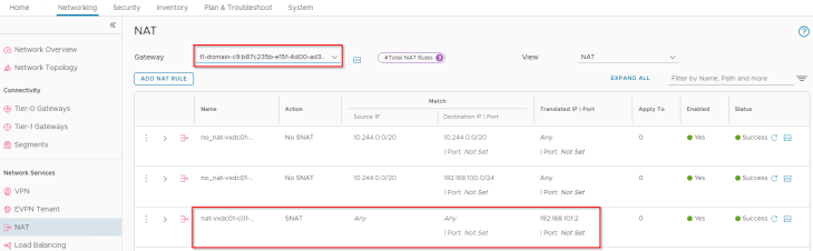
Since we have NAT mode enabled for the vSphere supervisor, we have an SNAT rule created under the namespace T1 gateway for outbound communication. Note that east-west communication between supervisor and vSphere namespaces will always happen with No-SNAT (We should see no-SNAT rules under the T1 gateways of supervisor and vSphere namespaces).
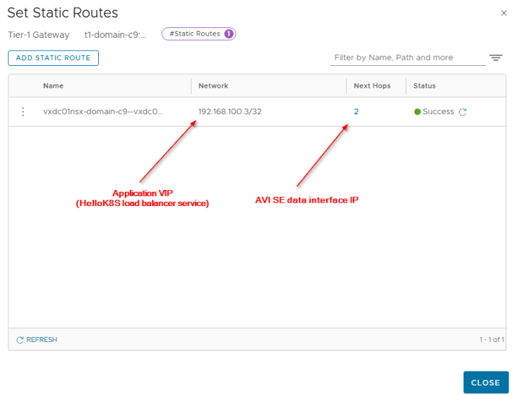
For each VIP created for the vSphere pods or TKG service clusters, a static route is programmed under the T1 gateway with next hop pointing to the data interface of AVI service engines.
Because we already advertised the Ingress and Egress networks from the T0 gateway with route aggregation, we see the summary route in the TOR physical fabrics.

Reviewing AVI objects
Now let’s review the AVI objects that are created by the workflow.
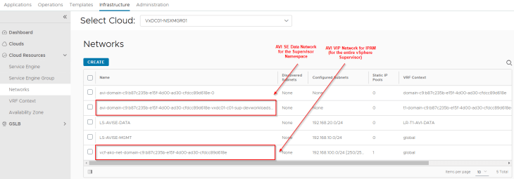
The dedicated T1 gateway created for the vSphere namespace and the AVI data segment will be added by the workflow as data networks to the AVI cloud connector.
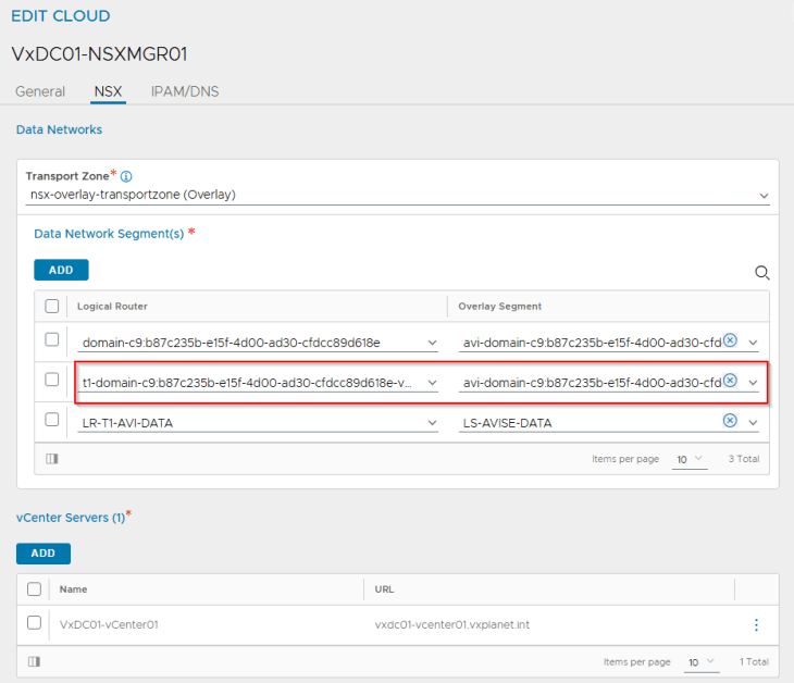
We will see two networks:
- AVI data network: As discussed previously, AVI SEs will work in a single arm mode under the NSX cloud connector. One SE interface will be consumed for each T1 gateway in the cloud connector and this interface will attach to the respective data network under the T1 gateway. DHCP is enabled on this data network (through segment DHCP in NSX)
- VIP network: Because we are inheriting the network settings from the supervisor, we should see the same IPAM network being used for the vSphere namespace.
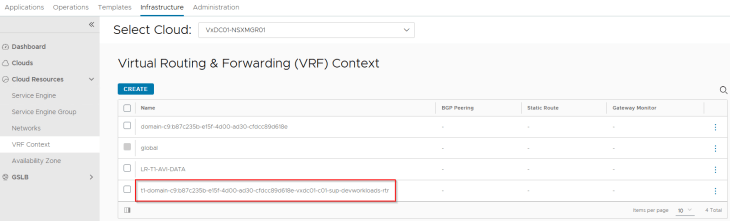
The namespace T1 gateway will be mapped as a VRF Context in AVI as per the NSX cloud connector design.
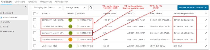
We should see the TKG service cluster VIPs and application VIPs (of vSphere pods) up and running in AVI (under the NSX cloud connector and on the namespace T1 VRF Context). Note that all the namespace VIPs (vSphere pods and TKG service clusters – L4) are created on the same service engine group of the supervisor.
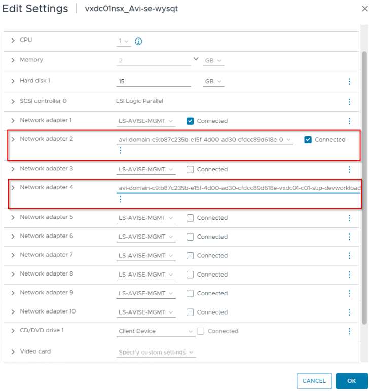
Reviewing the SE interface details, we see that one SE interface is consumed for the supervisor T1 gateway and another SE interface is consumed for the namespace T1 gateway. Additional SE interfaces will be consumed as and when new vSphere namespaces are created.
TKG Service Clusters and AKO
AKO is installed into the vSphere supervisor during the supervisor activation process. Whenever a TKG service cluster is created in a vSphere namespace, it uses paravirtualization to relay requests of type “load balancer” to the AKO instance in the vSphere supervisor where it is realized as L4 virtual services in the AVI load balancer. This paravirtualization doesn’t support Ingress, and an Ingress controller need to be installed manually on the TKG service clusters to support L7 services.
Below are the caveats of this integration:
- L4 VIPs (service of type loadbalancer) of all TKG service clusters (from all vSphere namespaces) lands into the default “admin” tenant in AVI – No multi-tenancy
- One SE group is used per vSphere supervisor and this SE Group will be shared across all the vSphere namespaces and TKG service clusters – No data plane isolation
- Services of type Ingress on the TKG service clusters will need to be handled by a different ingress controller (Contour, manual AKO install etc) – Manageability overhead
The above caveats can be overcome through a custom install of AKO manually on the TKG service clusters. Starting AKO 1.12.1, there is support for “loadbalancer class” field in the loadbalancer service spec, which can be used to instruct the cloud provider in the TKG service cluster to ignore load balancer requests from relaying to the supervisor AKO and instead use the service cluster AKO to provision load balancer (L4) objects.
Here is a quick overview of the AKO install process. We are not covering the lab implementation for AKO in this article, and will be taken as a separate blog series later.
- Install AKO using Helm on the TKG service clusters as per the below official documentation:
https://techdocs.broadcom.com/us/en/vmware-security-load-balancing/avi-load-balancer/avi-kubernetes-operator/1-13/avi-kubernetes-operator-guide-1-13/install-avi-kubernetes-operator.html
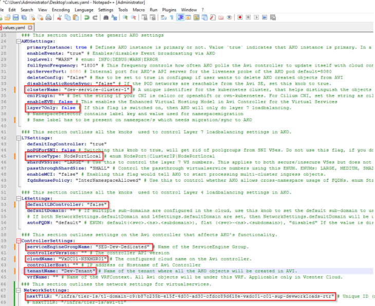
- Edit the values.yaml file and update the below settings as per the requirements
- clusterName: unique name for the AKO cluster
- layer7Only: This need to be set to “False” to allow service cluster AKO handle L4 requests
- serviceType: To define the AKO Ingress type. NodePortLocal mode is recommended if the TKG service cluster CNI is Antrea.
- L4 defaultLBController: This need to be set to “False” to allow service cluster AKO handle L4 requests using the loadbalancer class.
- serviceEngineGroupName: A custom SE Group name if a dedicated SE Group need to be assigned to the TKG service cluster (if data plane isolation is a requirement)
- tenantName: A custom tenant name if all L4 and L7 VIPs need to be steered to a specific AVI tenant (if AVI multitenancy is a requirement)
- nsxtT1LR: The T1 LR ID that will determine the VRF context under which the VIP will be created. Ideally, this will be the T1 gateway created by NCP for the vSphere namespace where the TKG service cluster is hosted.
- A sample values.yaml file with the above settings populated is as below:
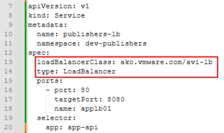
- To allow service cluster AKO handle all L4 requests (service type load balancer), we need to specify the load balancer class for every LB service that is created in the TKG service cluster. For this, the flags “layer7Only “ and “L4 defaultLBController “ in the values.yaml file (discussed above) has to be set to “false”. An example spec is as below:
For more information on Loadbalancer class and support with AKO, please check out the official documentation below:
https://techdocs.broadcom.com/us/en/vmware-security-load-balancing/avi-load-balancer/avi-kubernetes-operator/1-12/avi-kubernetes-operator-guide-1-12/l4/loadbalancerclass-support-for-lb-services-with-ako.html
Now let’s discuss an important topic – Isolate control plane traffic and data plane traffic for the TKG service clusters
Isolating control plane and data plane traffic for TKG service clusters
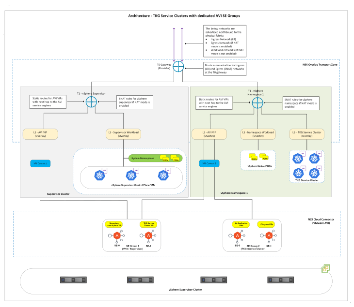
As discussed above, we have an option to specify a dedicated SE Group in the values.yaml file while installing AKO for the TKG service clusters. This is an important design consideration especially if we need to isolate control plane traffic and data plane traffic. With this approach, the SE Group for the supervisor will only host the control plane VIPs (Supervisor Kube-API, Service cluster Kube-API, CSI-VIP etc) and the SE Groups for TKG service clusters will host the L4 and L7 Ingress VIPs (data plane), as shown below.
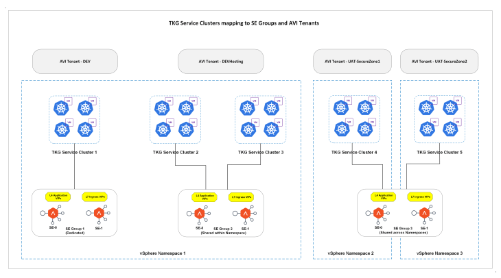
At scale, we could map TKG service clusters to dedicated or shared SE Groups within vSphere namespaces or across vSphere namespaces as below, and with mapping to AVI Tenants we could achieve multitenancy with RBAC policies for the hosted L4/L7 Ingress VIPs.
Okay, let’s conclude this chapter and will meet in Part 5 where we discuss about vSphere namespaces overriding supervisor network settings with custom Ingress and Egress networks. Stay tuned!!!
I hope the article was informative.
Thanks for reading

Continue reading? Here are the other chapters of this series:
Part 1: Architecture and Topologies
https://vxplanet.com/2025/04/16/vsphere-supervisor-networking-with-nsx-and-avi-part-1-architecture-and-topologies/
Part 2: Environment Build and Walkthrough
https://vxplanet.com/2025/04/17/vsphere-supervisor-networking-with-nsx-and-avi-part-2-environment-build-and-walkthrough/
Part 3: AVI onboarding and Supervisor activation
https://vxplanet.com/2025/04/24/vsphere-supervisor-networking-with-nsx-and-avi-part-3-avi-onboarding-and-supervisor-activation/


