
NSX introduced support for GRE tunnels on the T0 / VRF gateways in version 4.1.2. GRE tunnel is a logical point-to-point connection between two routing devices (or endpoints) where the traffic is encapsulated and transmitted over an IP network. With the support for GRE tunnels, we now have options for additional traffic paths into and outside of SDDC.
GRE implementation in NSX comes with the below considerations:
- GRE tunnels are supported only on A/S or stateless A/A T0 / VRF gateways. Stateful A/A T0 gateways are not supported.
- Only static routes or BGP can be used on the GRE tunnel. OSPF is not currently supported.
- BFD is supported on the GRE tunnels for failure detection.
- Stateful services over GRE is not currently supported.
In this two-part blog series on NSX GRE tunnels, we will cover the below topics:
Part 1: Inter-T0 GRE tunnel setup and BGP configuration over GRE
Part 2: Failure detection methods
Let’s get started:
Current environment
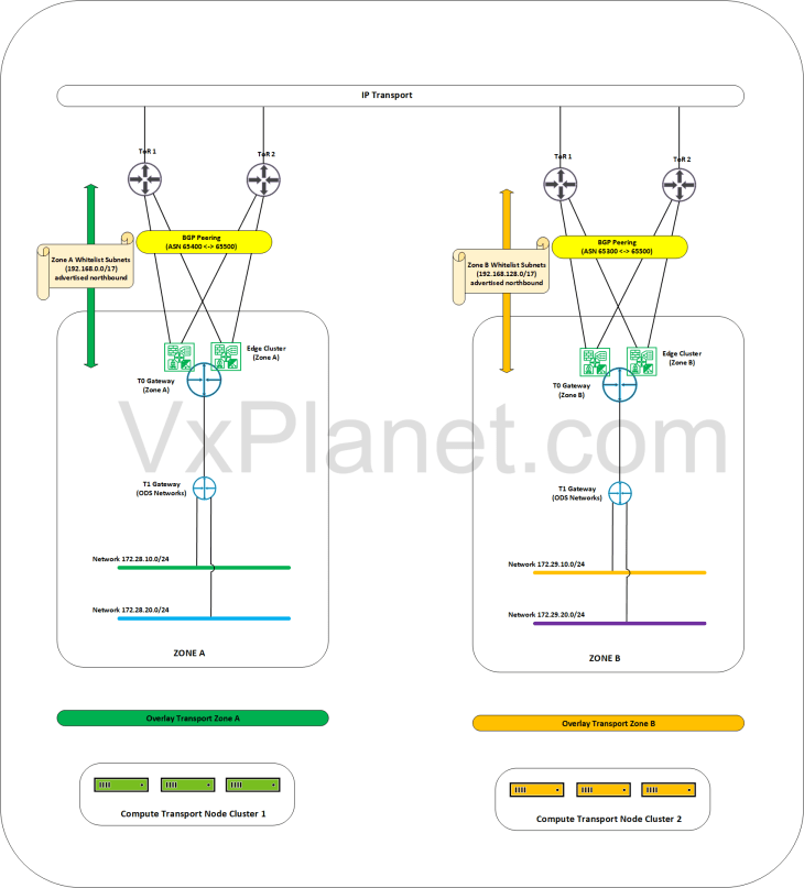
Let’s demonstrate GRE configuration using an use-case from a fictitious customer environment. Customer Corp-XYZ has a single instance NSX implementation across two zones – Zone A and Zone B. Zone A and Zone B are isolated from each other, they are hosted on dedicated vSphere clusters and are L3 isolated using separate NSX overlay transport zones. The edge clusters for both zones are hosted on a shared management and edge vsphere cluster where they establish BGP peering with the ToR switches for N-S reachability. They currently have route filters applied to the BGP neighbor configuration wherein only whitelisted networks (currently 192.168.0.0/16) are advertised outside of SDDC.
Zone A has a private testing network (called ODS environment) hosted under a dedicated T1 gateway. Networks for the ODS environment do not fall under the whitelisted subnet range, they are not advertised to the external fabrics and hence don’t have external access.
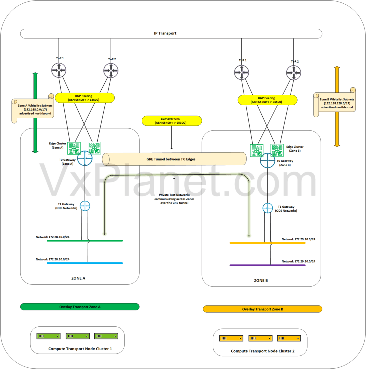
The ODS environment is now planned to be scaled out to Zone B and the requirement from Corp-XYZ is to establish connectivity for the private testing networks in the ODS environment to talk to each other across both zones over a dedicated path. We accomplish this with GRE tunnels between the zones and with BGP over GRE for dynamic route advertisement. Let’s do that shortly.
The below sketch depicts the current topology:
The below sketch shows the target topology after we have established GRE tunnels across zones.
Now let’s do a walkthrough of the current configuration:
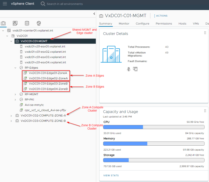
Zone A is hosted on the compute cluster “VxDC01-C02-COMPUTE-ZONE-A”. Zone B is hosted on the compute cluster “VxDC01-C03-COMPUTE-ZONE-B”. As stated earlier, we have a shared management and edge vsphere cluster named “VxDC01-C01-MGMT” where the edge clusters of both zones are hosted:
Zone A Edge cluster has two edge nodes:
- VxDC01-C01-Edge01-ZoneA
- VxDC01-C01-Edge02-ZoneA
and same for Zone B:
- VxDC01-C01-Edge03-ZoneB
- VxDC01-C01-Edge04-ZoneB
The zones are hosted on separate overlay transport zones in NSX.
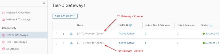
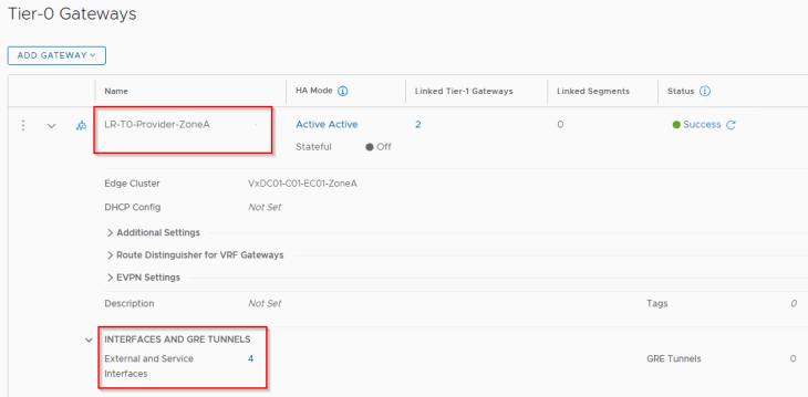
The T0 Gateways of the zones are as follows:
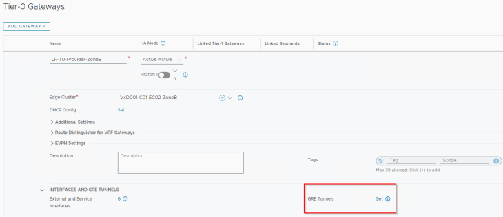
- LR-T0-Provider-ZoneA (for Zone A)
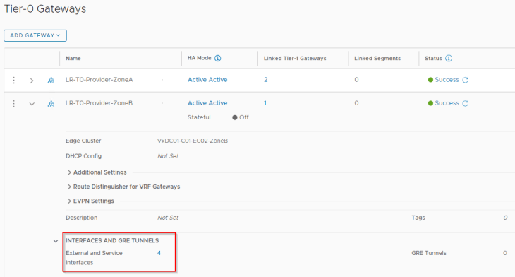
- LR-T0-Provider-ZoneB (for Zone B)
Zone A T0 gateway is hosted on BGP ASN 65400 with peering to ToR switches over VLANs 1006 and 1007.
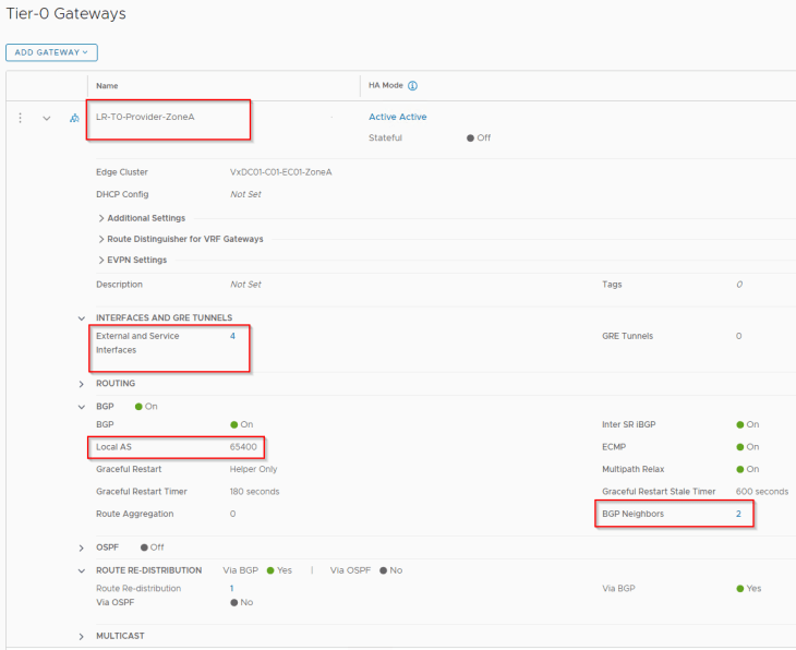
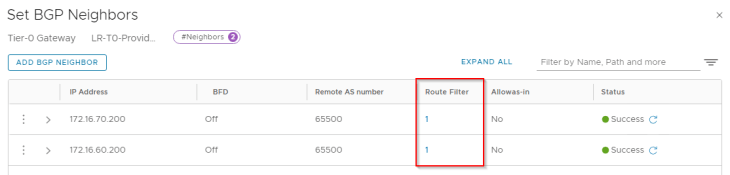
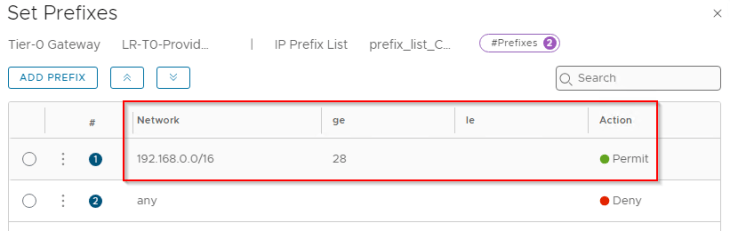
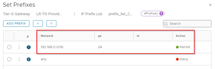
As stated earlier, we have route filters applied to the BGP neighbor configuration that allows only the whitelisted network 192.168.0.0/17 to be advertised to the physical fabrics.
Similarly, Zone B T0 gateway is hosted on BGP ASN 65300 with peering to ToR switches over the same VLANs 1006 and 1007.
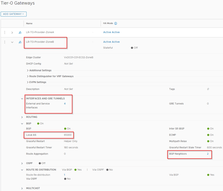
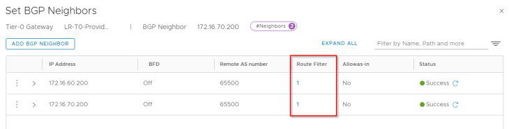
We have route filters applied to the BGP neighbor peering that allows only the whitelisted network 192.168.0.128/17 to be advertised to the physical fabrics.
Below are the private testing networks of the ODS environment that are hosted across the zones. Note that they are on separate overlay transport zones.
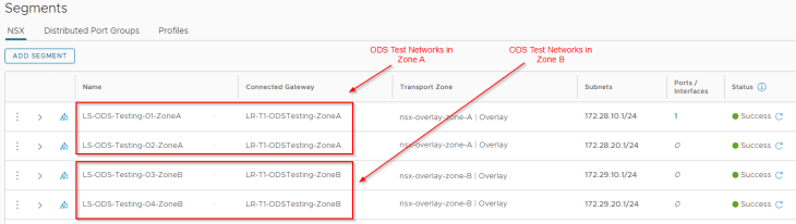
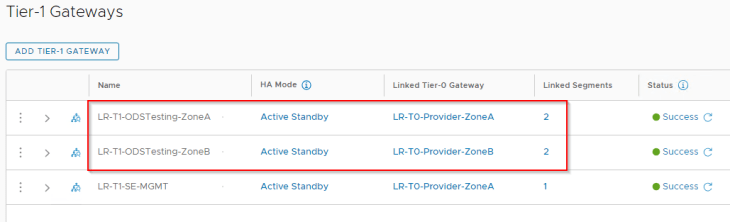
These testing networks attach to their respective T1 gateways in the zones.
Next, we will do the configuration of GRE tunnels so that the private testing networks can talk to each other across the zones, A and B.
Creating loopback interfaces for GRE tunnel endpoints
GRE tunnel endpoints perform the encapsulation and decapsulation of the packets. Source GRE TEP encapsulates the packets, adds the GRE header and forwards the packet to the destination GRE TEP who performs the decapsulation and routes the packet to the final destination.
The tunnel endpoints for GRE should point to either an external interface or any loopback interface on the T0 gateway. For this blog post, we will prefer using loopback interfaces for the GRE tunnel endpoints. This is because we have multiple uplinks on the edge nodes, and using a loopback interface will ensure that we have redundant paths to reach the GRE tunnel endpoint interface even if one of the uplinks goes down.
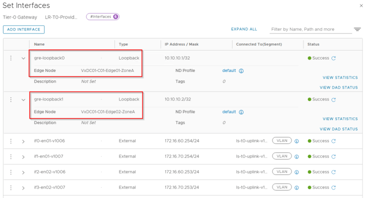
Let’s create two loopback interfaces – one per edge node on each zone:
For Zone A:
- gre-loopback0 : on edge node 1 (10.10.10.1/32)
- gre-loopback1 : on edge node 2 (10.10.10.2/32)
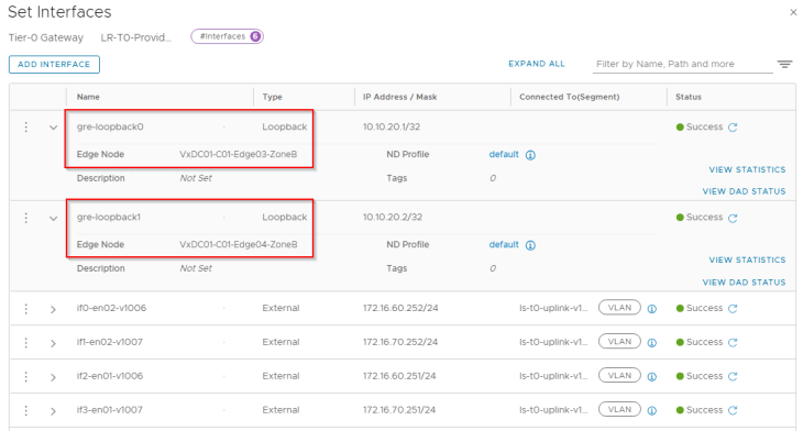
and for Zone B:
- gre-loopback0 : on edge node 1 (10.10.20.1/32)
- gre-loopback1 : on edge node 2 (10.10.20.2/32)
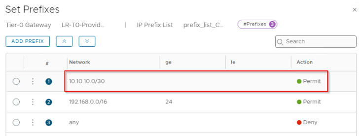
Now let’s whitelist the loopback interfaces so that they are advertised to external fabrics and are reachable to both zones. We will update the prefix list that is added to the route filter, with the loopback subnet.
For Zone A:
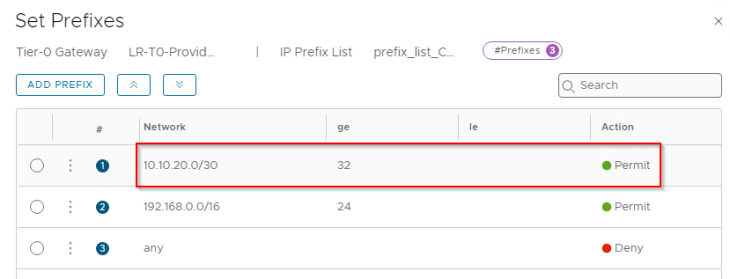
For Zone B:
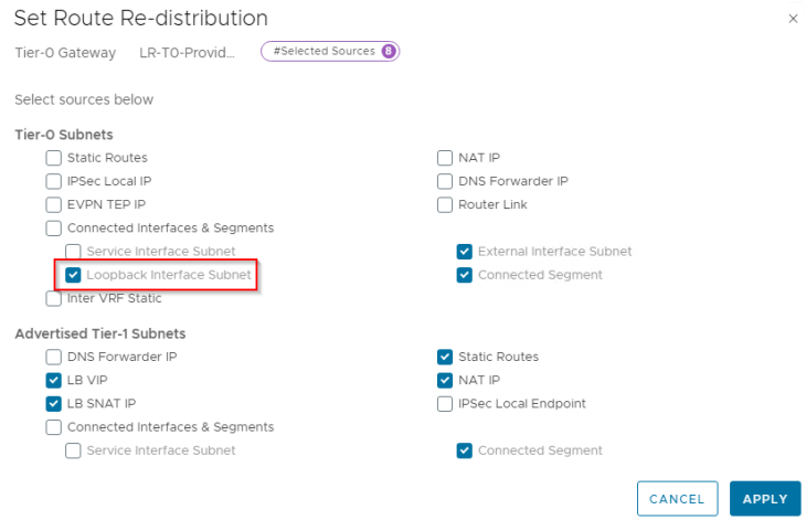
We also need to redistribute the loopback subnet into BGP on both zones.
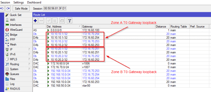
and finally, we see that the loopback subnets are advertised successfully to the ToR switches and are reachable to both zones.
Creating Inter-T0 GRE tunnels
Now that we have the GRE tunnel endpoint interfaces created, we will establish GRE tunnels between Zone A and Zone B. Below is a logical sketch that shows the GRE tunnels we need to create between Zone A and Zone B. If we closely examine the logical sketch below, we will require four GRE tunnels in total, where an edge node in a zone establishes a GRE tunnel to each of the edge nodes in the other zone.
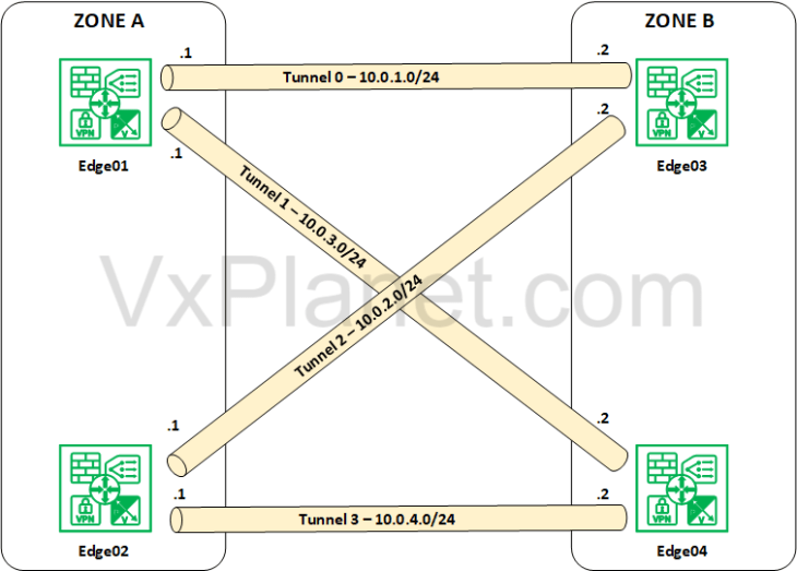
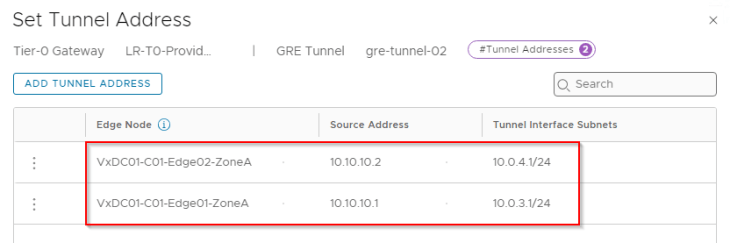
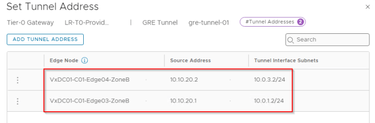
Tunnel 0 -> between Zone A Edge01 and Zone B Edge 03 on Tunnel subnet 10.0.1.0/24
Tunnel 1 -> between Zone A Edge01 and Zone B Edge 04 on Tunnel subnet 10.0.3.0/24
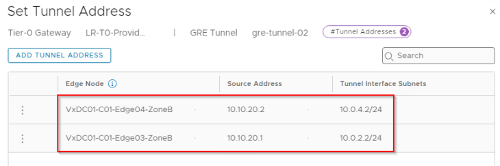
Tunnel 2 -> between Zone A Edge02 and Zone B Edge 03 on Tunnel subnet 10.0.2.0/24
Tunnel 3 -> between Zone A Edge02 and Zone B Edge 04 on Tunnel subnet 10.0.4.0/24
Note : In fact, you don’t need a /24 mask for the tunnel subnet. Ideally a /30 mask should be good as it is a point-to-point connection.
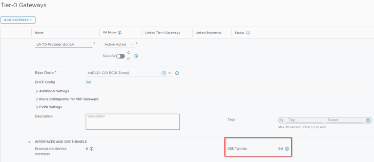
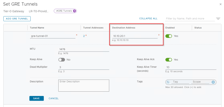
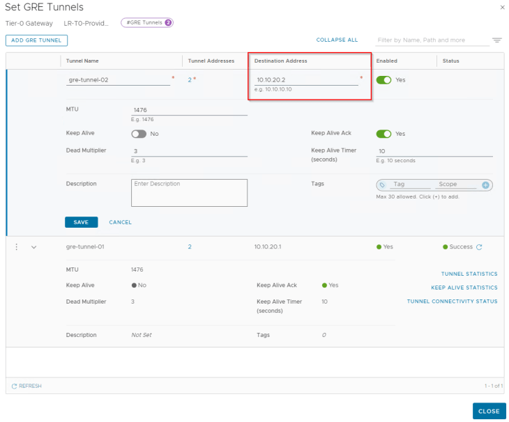
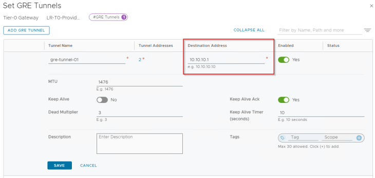
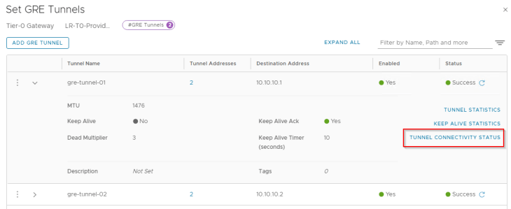
Let’s connect to the T0 gateway on Zone A and create the GRE interfaces. For this blog post, we will keep the GRE Keepalives to disabled, and will discuss more about failure detection methods in Part 2.
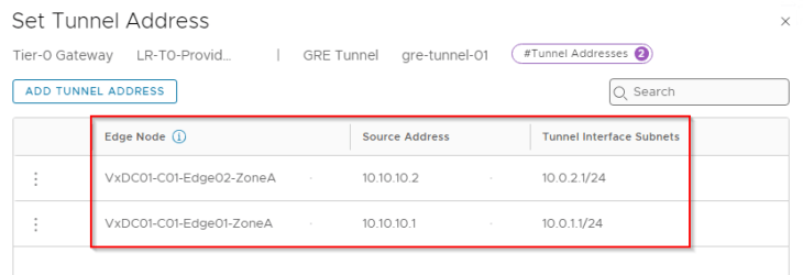
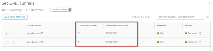
Below are the two GRE tunnels to the remote endpoint 10.10.20.1 (Edge node 03 in Zone B)
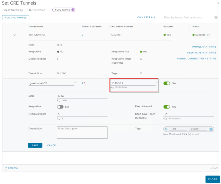
Below are the two GRE tunnels to the remote endpoint 10.10.20.2 (Edge node 04 in Zone B)
At this moment, we have the four GRE interfaces on Zone A T0 gateway created.
Now let’s connect to the T0 gateway on Zone B and create the GRE interfaces:
Below are the two GRE tunnels to the remote endpoint 10.10.10.1 (Edge node 01 in Zone A)
Below are the two GRE tunnels to the remote endpoint 10.10.10.2 (Edge node 02 in Zone A)
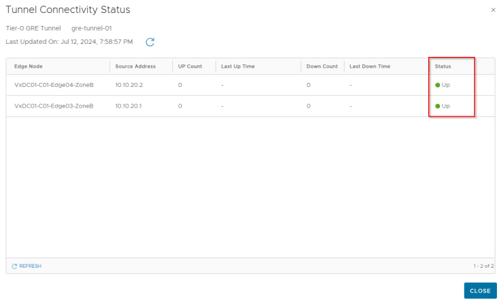
GRE tunnels are stateless in nature, that means failure of the tunnel interface at one end will not dynamically update the tunnel status at the other end unless any keepalive mechanism is in place. As we haven’t enabled GRE keepalives on the tunnel, the tunnel connectivity status always shows up.
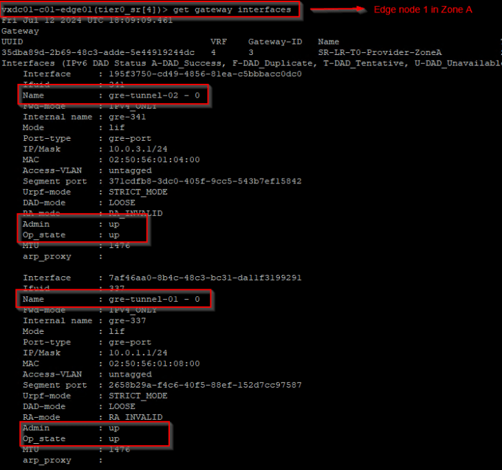
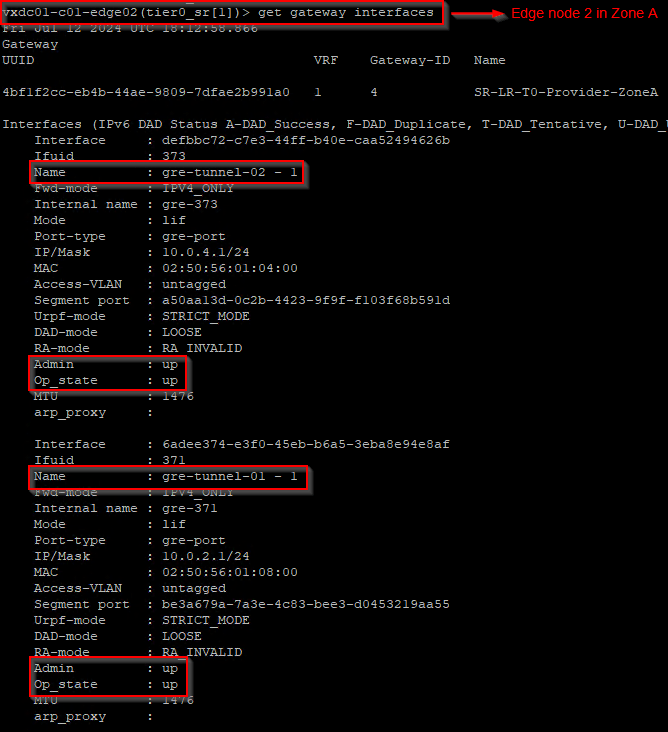
Let’s verify the GRE interfaces created on the edge nodes in both zones.
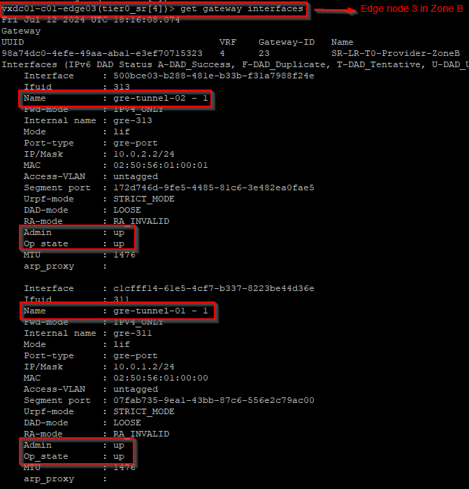
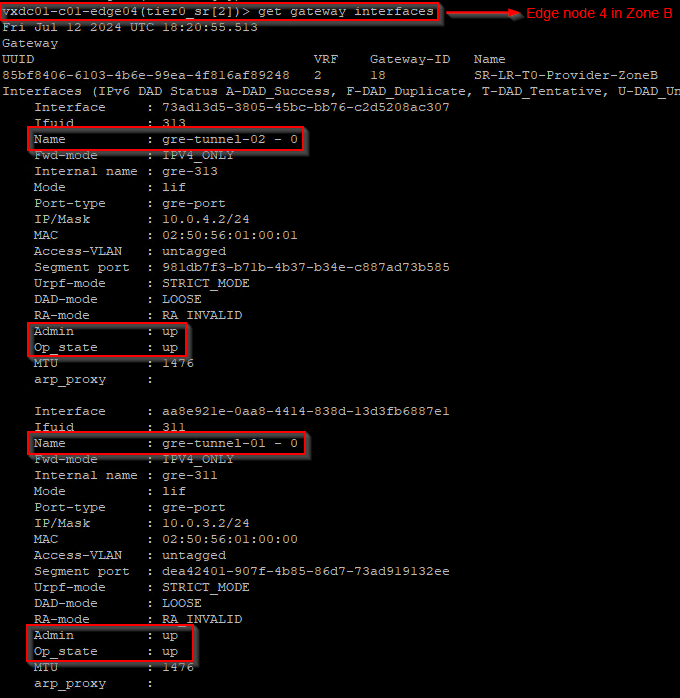
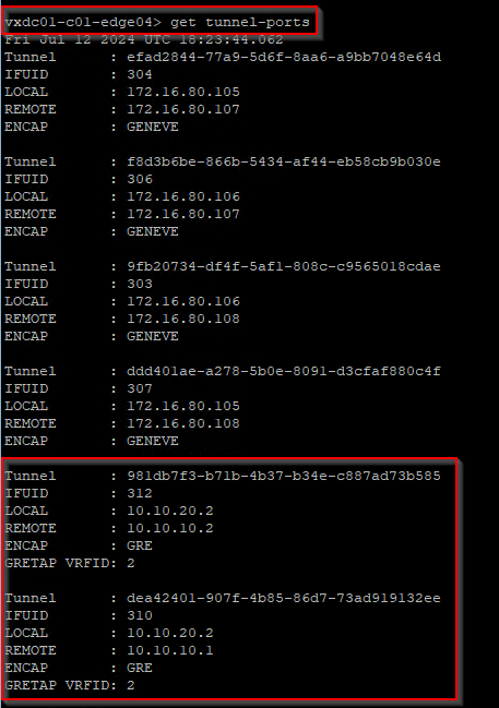
Let’s also verify the GRE tunnels from the edge CLI. Below is from Edge node 4.
Configuring BGP over GRE
As of NSX 4.1.2, the only dynamic routing protocol that is supported over NSX implementation of GRE is BGP. We will now establish BGP peering from Zone A edge nodes to Zone B edge nodes using the GRE tunnel interface IP addresses. Note that Zone A is on ASN 65400 and Zone B is on ASN 65300.
For this blog post, we will set BFD to disabled, and will discuss more about failure detection methods in Part 2.
Let’s connect to the T0 gateway in Zone A and configure BGP neighborship to the remote tunnel IPs in Zone B.
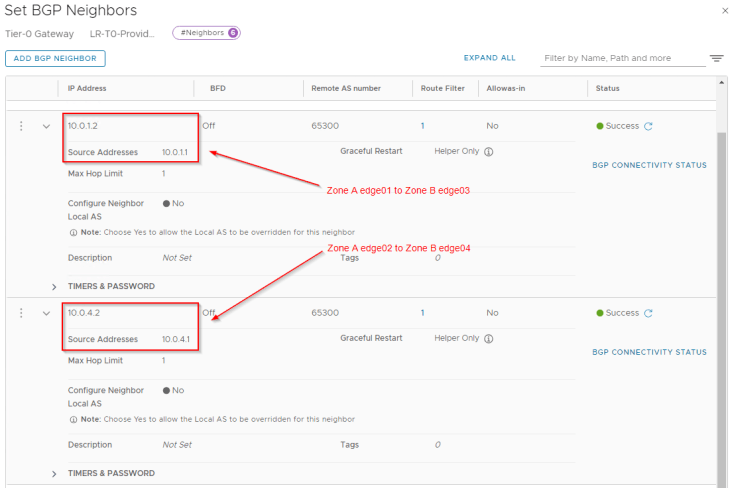
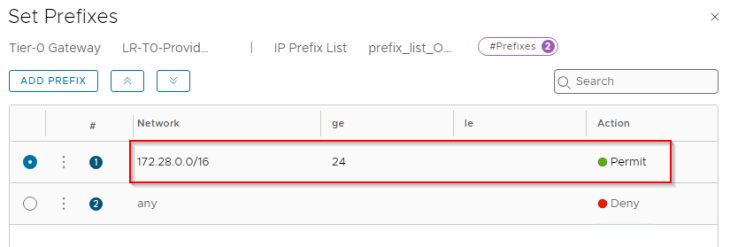
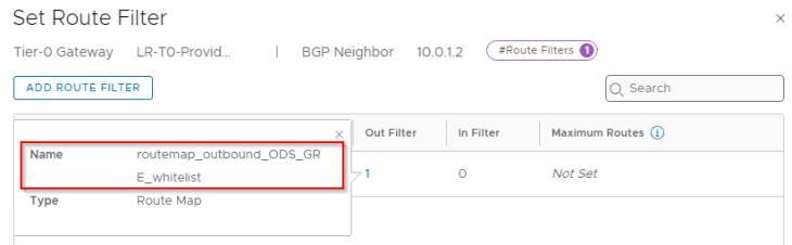
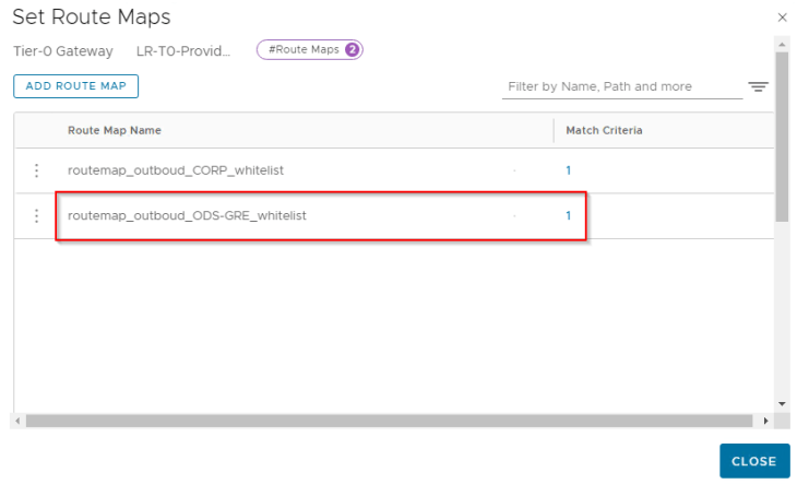
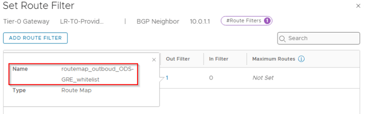
For each of the BGP neighbor relationship, we will add an outbound route filter to make sure that only the private testing subnets (172.28.0.0/16 for Zone A) are advertised over the GRE tunnels. We also need to make sure that the GRE tunnel endpoint IP addresses (10.10.10.1/32, 10.10.10.2/32) are NEVER advertised over this GRE tunnel as this would result in a routing loop. This phenomenon is called GRE tunnel recursive routing.

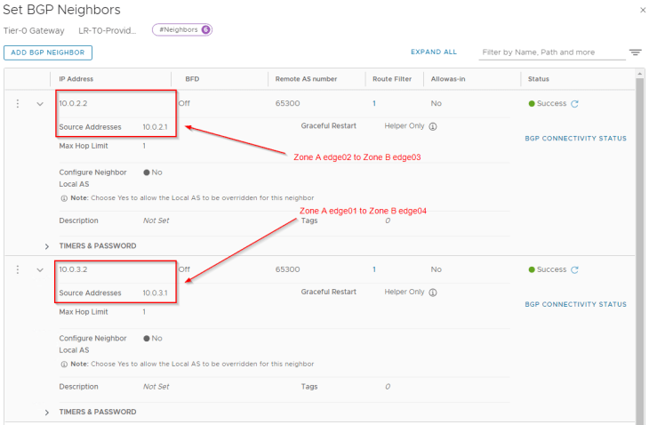
Now let’s connect to the T0 gateway in Zone B and configure BGP neighborship to the remote tunnel IPs in Zone A.
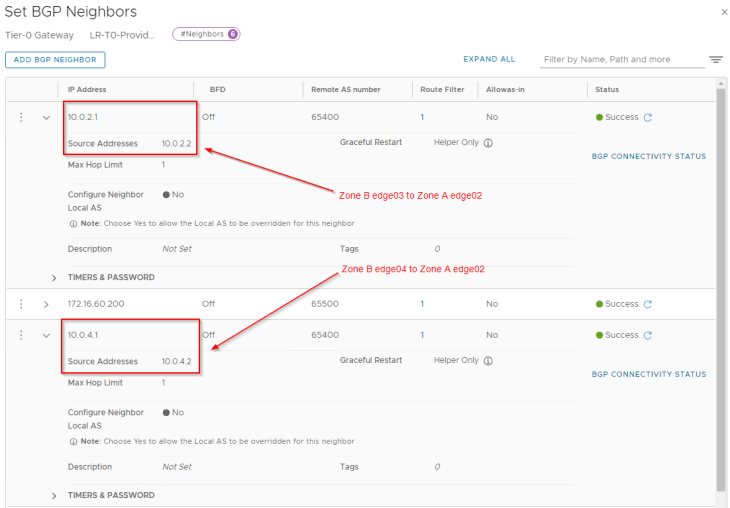
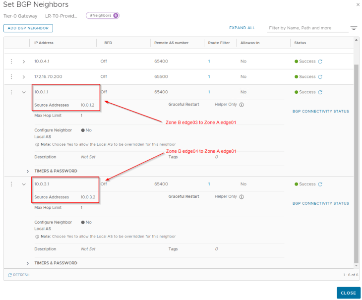
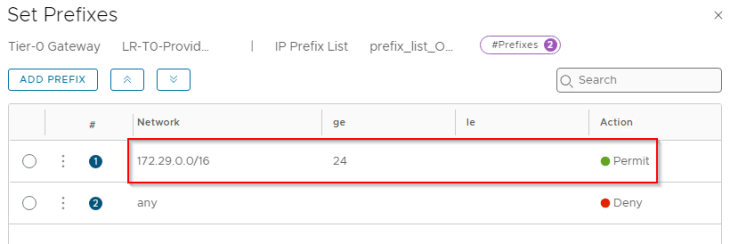
We will add an outbound route filter to make sure only the private testing subnets (172.29.0.0/16 for Zone B) are advertised over the GRE tunnels. Similar to Zone A, we need to make sure that the GRE tunnel endpoint IP addresses (10.10.20.1/32, 10.10.20.2/32) are NEVER advertised over this GRE tunnel.
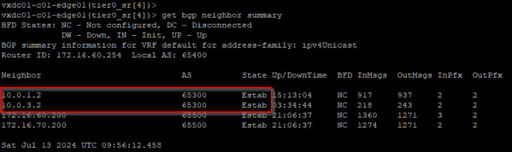
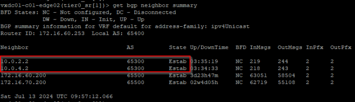
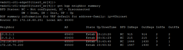
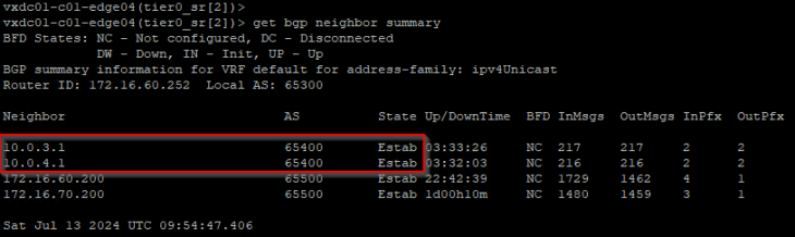
Now let’s confirm that the BGP peering status on both Zones are successful.
Validating inter-zone reachability for the private testing networks
Now let’s review the BGP table on the edges and confirm that the remote testing networks of the ODS environment are learned successfully.
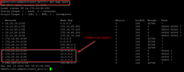
The below table is from edge node 02 (Zone A) and we see that the prefixes from Zone B – 172.29.x.x are learned successfully over the GRE tunnel.
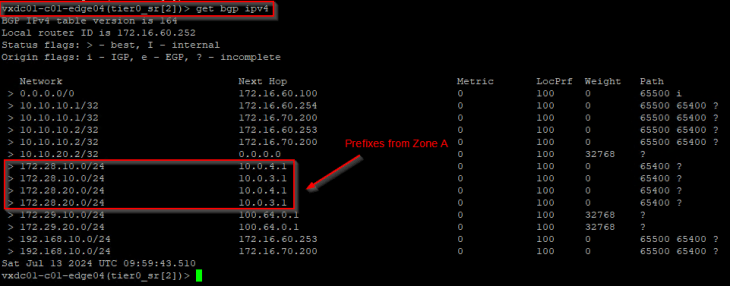
The below table is from edge node 04 (Zone B) and we see that the prefixes from Zone A – 172.28.x.x are also learned successfully.
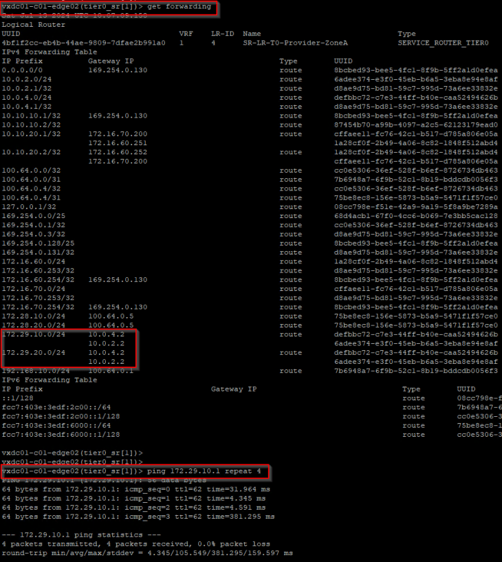
Forwarding table on edge node 02 (Zone A) shows two ECMP paths to the remote testing networks 172.29.10.0/24 and 172.29.20.0/24, over the GRE tunnel via edge node 03 and edge node 04 in Zone B.
Let’s perform a connectivity test to 172.29.10.1.
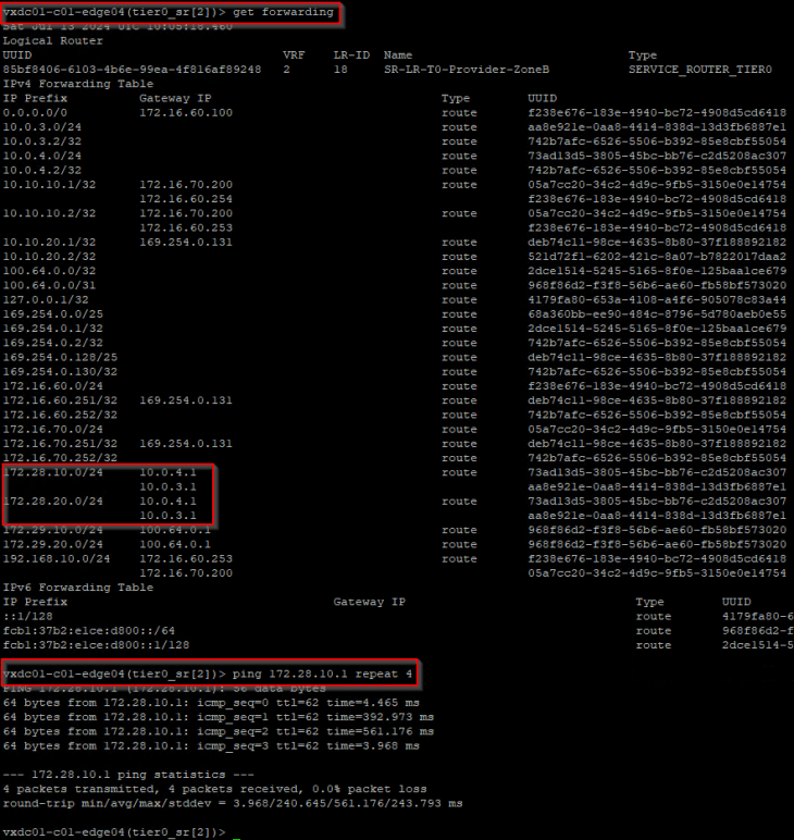
Similarly forwarding table on edge node 04 (Zone B) shows two ECMP paths to the remote testing networks 172.28.10.0/24 and 172.28.20.0/24, over the GRE tunnel via edge node 01 and edge node 02 in Zone A.
Let’s perform a connectivity test to 172.28.10.1.
SUCCESS!!! The private testing networks of the ODS environment in Zone A and Zone B now has reachability with each other over the GRE tunnel. Each zone also has redundant paths to reach the remote testing network on the other zone, such that failure of an edge node will not impact the ODS environment. Note that, we haven’t enabled failure detection mechanisms on the GRE tunnel, we will cover that in Part 2.
Let’s break for now and will meet in Part 2 shortly. Stay tuned!!!
I hope the article was informative.
Thanks for reading.

Continue reading? Here are the other parts of this series:
Part 2 – Failure Detection :
https://vxplanet.com/2024/07/22/nsx-gre-tunnels-part-2-failure-detection/


