
Welcome to Part 2 of the blog series on vSphere Supervisor networking with NSX and AVI. In the previous article, we discussed the networking and load balancing architecture covering the different topologies for supervisor clusters, vSphere namespaces with custom network topologies, multiple supervisor clusters and zonal supervisors.
In this article, we will do a walkthrough of the current environment and it’s build details to support the deployment of vSphere supervisor and namespaces to cover the contents till chapter 7. We will scale out the infrastructure with additional vSphere clusters as we do chapter 8 and above.
If you missed the Part 1 of this series, please check out below:
Part 1: Architecture and Topologies
https://vxplanet.com/2025/04/16/vsphere-supervisor-networking-with-nsx-and-avi-part-1-architecture-and-topologies/
Let’s get started:
vSphere Environment Walkthrough
The current vSphere environment where we plan to activate vSphere supervisor is a collapsed management, compute and edge vSphere cluster hosting the management workloads, compute workloads and NSX edge clusters under dedicated vSphere resource pools.
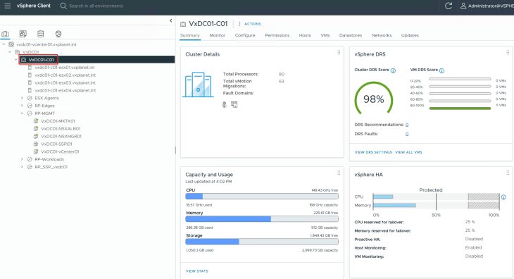
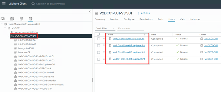
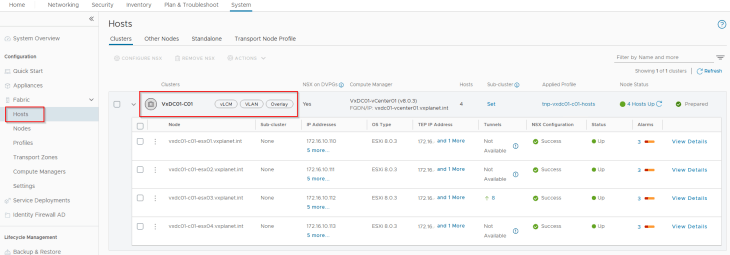
The vSphere cluster ‘VxDC01-C01 ‘ has 4 ESXi hosts, each with 2-pnic networking managed by a single VDS. All the pre-requisite networking including the necessary vCenter port groups are created.
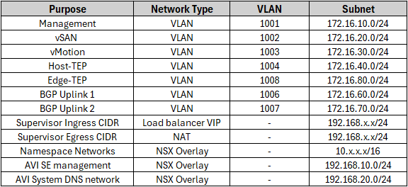
The below table summarizes the subnet details used for the deployment:
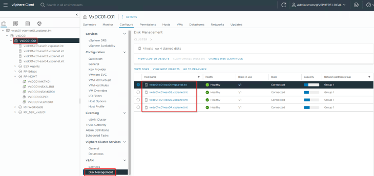
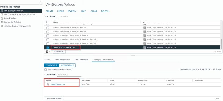
The storage layer is backed by vSAN ESA. A custom vSAN storage policy is created to support vSphere supervisor activation.
NSX Walkthrough
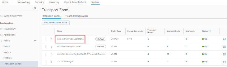
This vSphere cluster VxDC01-C01 is prepared for NSX Overlay using a transport node profile.
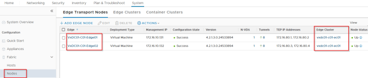
We have an edge cluster hosted on this vSphere cluster that will be used to host the T1 and T0 gateways of vSphere supervisor and namespaces.
We have a single Provider T0 gateway where all the T1 gateways of vSphere supervisor and namespaces attach to. Due to limited resources in my home lab, this provider T0 gateway will also handle the management traffic for the AVI SEs and System DNS (Remember the dedicated T0 management gateway we discussed in Part 1? We won’t be using this in our deployment.)
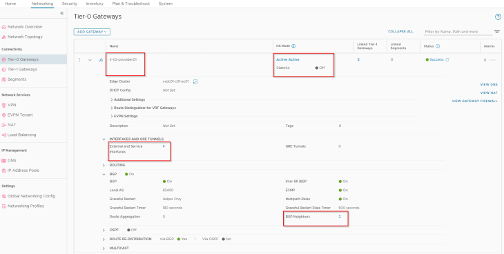
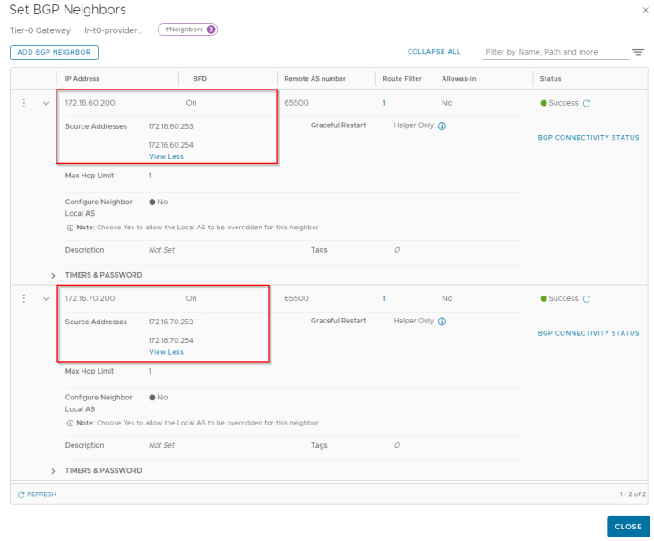
This T0 gateway establishes BGP peering with the TOR switches over its four external interfaces – two via edge node 1 and two via edge node 2.
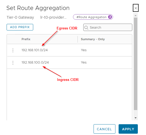
For the Ingress and Egress CIDR that will be used for the vSphere supervisor and namespaces, we have configured route aggregation at the T0 gateway to allow only the summary addresses to be advertised northbound (and not the /32 host routes).
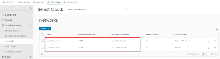
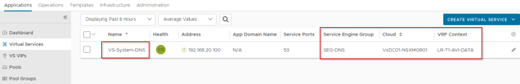
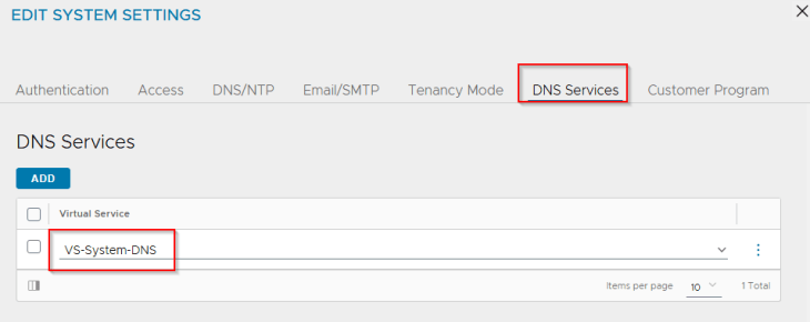
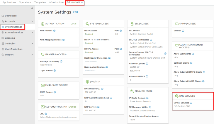
We have two T1 gateways created – one for the AVI management traffic and the other for AVI System DNS traffic. The T1 gateway and segment for AVI System DNS is used to handle the DNS traffic of Ingress services for the TKG service clusters if we use AVI AKO as the Ingress controller. This is not required if a different Ingress controller like Contour is used.
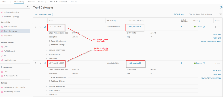
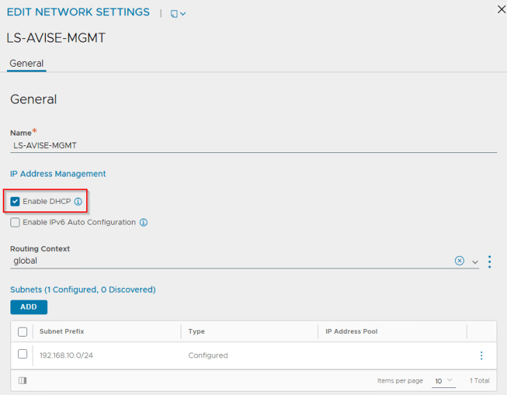
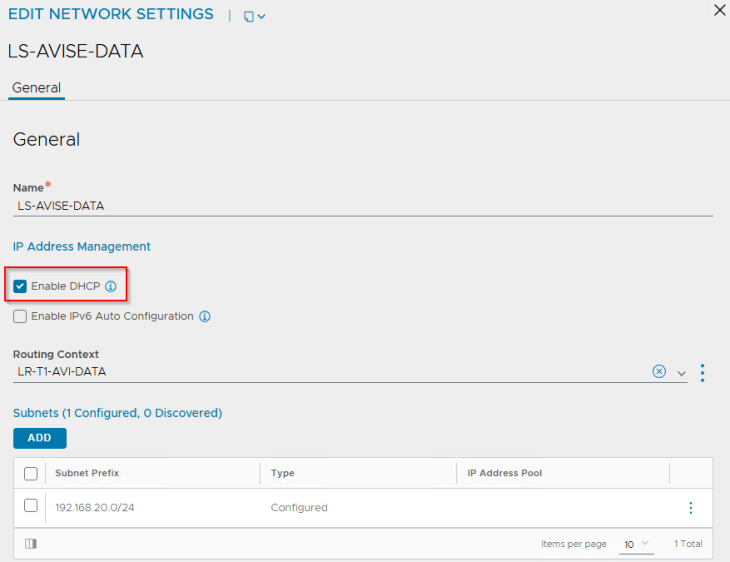
We have two segments created – one for AVI management traffic and the other for AVI System DNS traffic, each attached to their respective T1 gateways, discussed above.
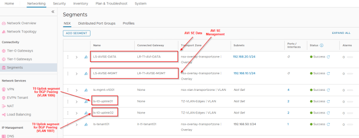
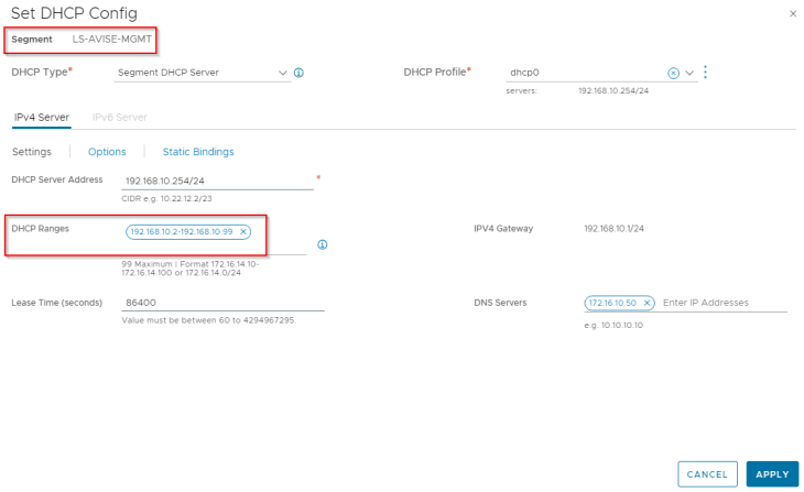
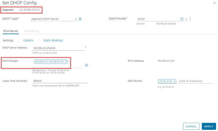
Both segments have DHCP enabled to automate the IP addressing for AVI service engines.
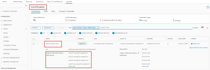
And finally, the NSX cluster certificate is replaced with an internal CA signed certificate. This is optional but is done as it’s a recommended practice.
VMware AVI Walkthrough
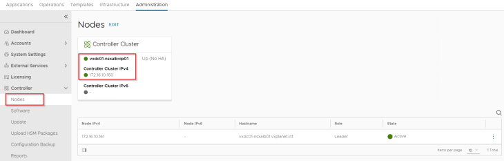
We have a single node AVI controller cluster deployed on the management VLAN subnet adjacent to the other management appliances (vCenter server, NSX manager etc)
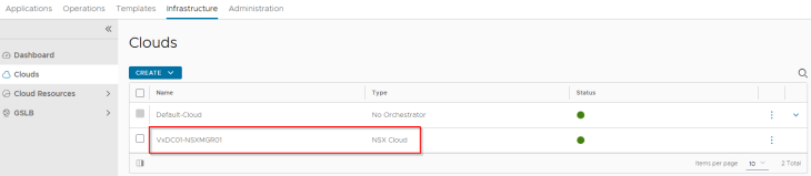
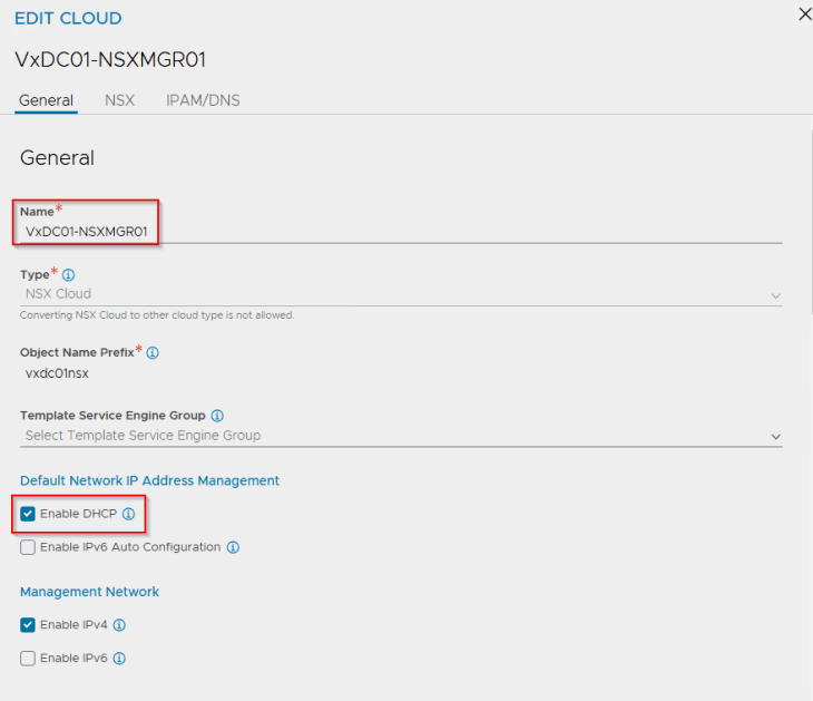
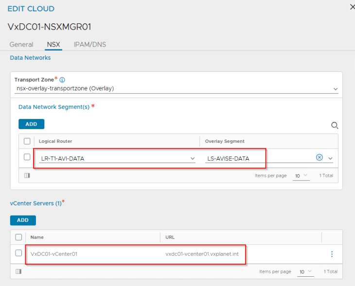
vSphere supervisor with NSX and AVI integration supports only the NSX cloud connector. We have an NSX cloud connector configured on the same NSX overlay transport zone that the vSphere cluster is configured on.
The supervisor / namespace creation workflow creates AVI data segments in NSX with segment DHCP enabled. Hence, we require DHCP to be enabled on the cloud connector. This is currently a requirement.
There will be only one management network definition per NSX cloud connector, and all SEs deployed under this cloud connector will inherit the same management settings. In our case, this will be the AVI management T1 gateway and segment that we configured previously in NSX.
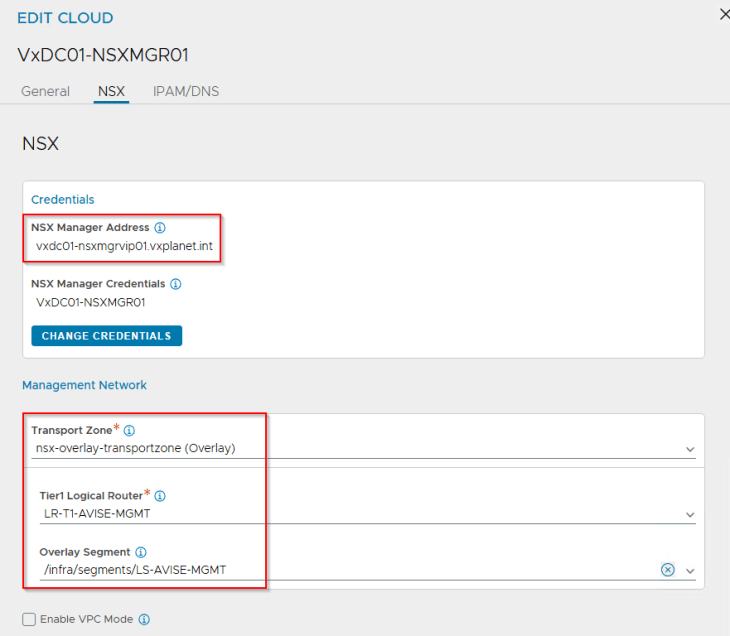
We define the AVI data networks where the SEs will attach to. For each supervisor / namespace T1 gateway that is created, the workflow will dynamically update the cloud connector with the respective data networks. For now, we will add the AVI System DNS T1 gateway and segment to the cloud connector.
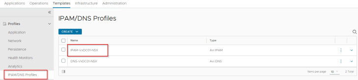
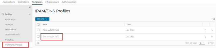
We also have an IPAM and DNS profile attached to the cloud connector.
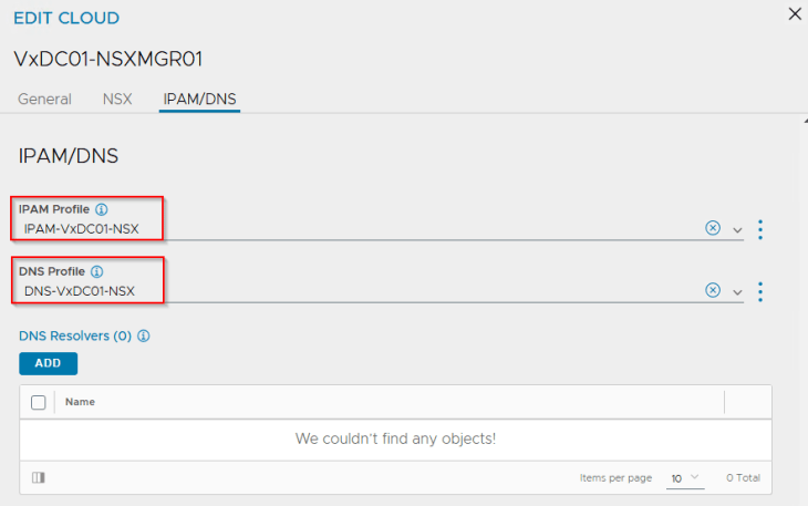
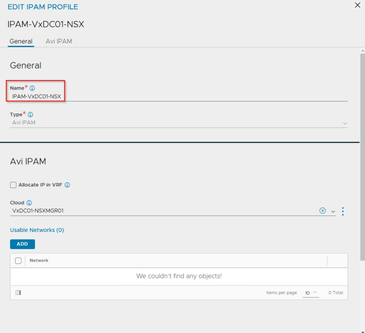
IPAM profile is used for dynamic assignment of VIPs for the K8S load balancer / ingress services and is mandatory for vSphere supervisor activation.
The IPAM profile is just a placeholder at this moment and is kept blank without any networks added to it. This IPAM profile will be dynamically updated with the network information (Ingress subnets) as part of vSphere supervisor and namespace activation workflows.
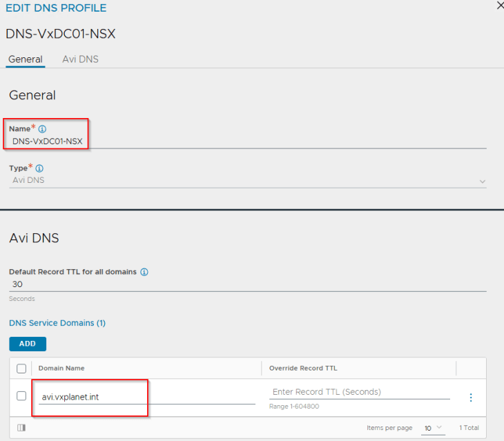
DNS profile is optional and is used only for the creation of Ingress services on the TKG service clusters if AKO is used as the Ingress controller. If the previously mentioned T1 Gateway and segment for AVI System DNS is not created, this DNS profile is not required.
DNS profile has the list of sub-domains where the Ingress FQDNs will be created. For each sub-domain, a delegation need to be created on the upstream DNS servers to the AVI DNS virtual service that will be authoritative for all the records under this subdomain.
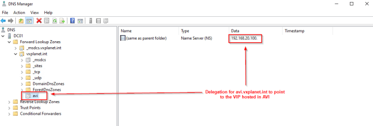
In our environment, we have an AD integrated parent DNS zone ‘vxplanet.int’ where the clients point to. We define a delegation for ‘avi.vxplanet.int’ from the parent zone to the DNS virtual service hosted in AVI, so that DNS requests from any clients tying to access the ingress services on subdomain ‘avi.vxplanet.int’ will be forwarded to the DNS virtual service in AVI. In this way, we can avoid manual DNS host record creation for ingress FQDNs every time they are created.
For each discovered network from the cloud connector (management and data networks), the appropriate subnet information is updated.
Because we had the flag for DHCP enabled in the NSX cloud connector, all the discovered networks should have DHCP enabled.
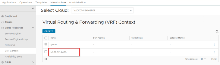
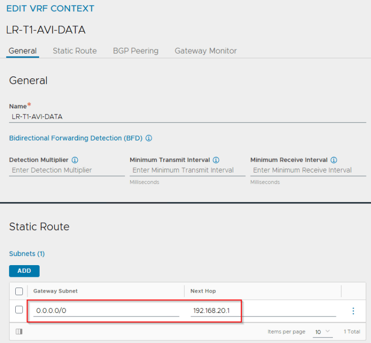
Each T1 gateway that is added as a data network to the NSX cloud connector will be mapped as a VRF context in AVI. If DHCP is not used, a static default route (default gateway) needs to be created for the VRF context.
Now lets discuss an important topic with the vSphere supervisor and AVI integration. This is about how the SE Group is configured for consumption.
vSphere Supervisor and SE Group selection
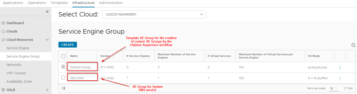
One SE Group will be created for a vSphere supervisor and will be shared across the supervisor and all the vSphere namespaces. This SE Group is created as a clone of the “Template SE Group” that is specified in the NSX cloud connector.
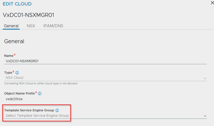
If there isn’t an SE Group specified under the “Template SE Group”, then the SE Group will be created as a clone of the “Default Group”. Hence it is very important to pre-configure this template SE Group with the correct HA mode, sizing and placement settings before activating vSphere supervisor, else the vSphere supervisor deployment will fail.
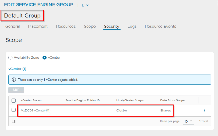
In our environment, we have the “Default Group” configured with the below settings:
- HA Mode : Active / Active
- Maximum SEs : 4
- VS scale factor : 2
- Sizing : 1vCPU / 2 GB Memory / 30 GB Storage
- Placement settings : Cluster VxDC01-C01 and vSAN datastore
Note that once the vSphere Supervisor workflow clones the template SE group or the “Default Group” to a new SE Group, any changes made to the template SE group or the Default-SE Group configuration will not reflect in an already created SE Group. We must modify the configuration for the existing cloned SE Group separately.
We have a second SE Group created to place the AVI System DNS virtual service. This DNS virtual service will host the DNS records of all the Ingress FQDNs that are created on the TKG service clusters.
That’s all for now, let’s meet in Part 3 to complete few other pre-requisites, AVI onboarding workflow, vSphere supervisor activation , and review of the topology that is getting deployed.
Stay tuned!!!
I hope the article was informative. Thanks for reading.

Continue reading? Here are the other parts of this series:
Part 1: Architecture and Topologies
https://vxplanet.com/2025/04/16/vsphere-supervisor-networking-with-nsx-and-avi-part-1-architecture-and-topologies/