Let’s continue our discussion around the topology for multiple vSphere supervisors with NSX and AVI. This is Part 9 and, in this article, we will discuss the second design option where each vSphere supervisor is prepared on a dedicated NSX overlay transport zone.
If you missed the previous article where we discussed about multiple vSphere supervisors on a shared NSX overlay transport zone and it’s caveats, please check it out from the link below:
Part 8: Multiple supervisors on shared NSX transport zone
https://vxplanet.com/2025/06/08/vsphere-supervisor-networking-with-nsx-and-avi-part-8-multiple-supervisors-on-shared-nsx-transport-zone/
Let’s get started:
vSphere supervisors on dedicated NSX transport zone
As discussed in Part 1 – Architecture and Topologies, below is the network architecture of two vSphere supervisors, each on a dedicated NSX overlay transport zone:
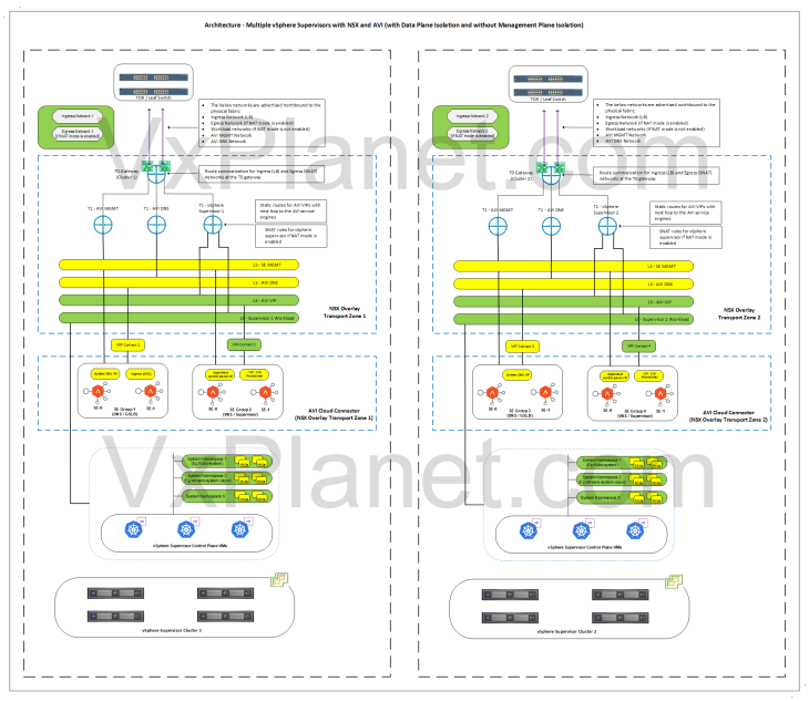
Below is a recap of what we discussed in Part 1:
- In this architecture, each vSphere supervisor cluster is configured on a dedicated NSX overlay transport zone. There is network isolation between the vSphere supervisors as the segments created for one supervisor are visible and consumable only by that specific vSphere supervisor.
- There will be dedicated T0 gateways for each vSphere supervisor.
- The T0 edge cluster of each vSphere supervisor will be co-located on the same vSphere cluster.
- Each supervisor will have dedicated service & pod CIDRs, namespace networks, ingress networks and egress networks
- There is a 1:1 mapping between an NSX overlay transport zone and AVI cloud connector. Hence each supervisor will use separate NSX cloud connectors in AVI.
- Because each supervisor has a dedicated NSX cloud connector in AVI, the AVI SE management network can use the same T0 gateway of the supervisor, as in the above architecture.
- A dedicated SE Group will be used per supervisor, and this SE group belongs to the respective NSX cloud connector.
- Optionally, a dedicated SE Group per vSphere supervisor can be used to host the system DNS for L7 Ingress / GSLB / AMKO use cases.
Let’s implement this:
Current Environment Walkthrough
vSphere walkthrough
I have uninstalled the vSphere supervisors and the related NSX / AVI objects that was created in the previous article, to re-use the same lab for this article. As earlier, we have two vSphere clusters: VxDC01-C01 and VxDC01-C02. All the pre-requisites for supervisor activation (including AVI onboarding workflow) are in place. Please check out Part 2 and Part 3 for more details around the pre-requisites.
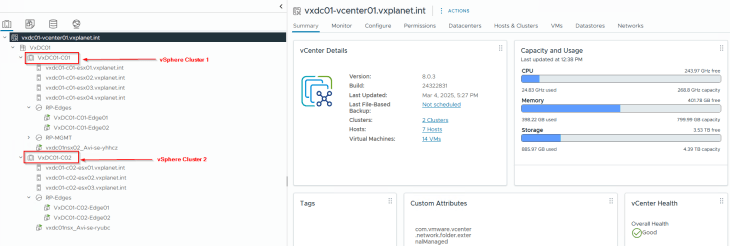
Both vSphere clusters are on dedicated vCenter VDS.
Note: You cannot have a shared VDS across the vSphere clusters in this case, as each vSphere cluster need to be prepared on separate NSX overlay transport zones.

NSX walkthrough
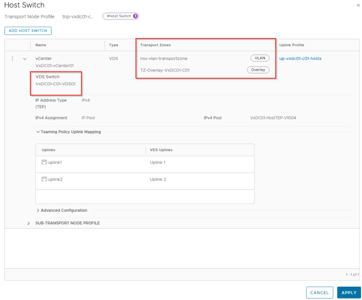
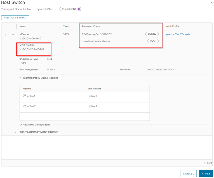
Both vSphere clusters VxDC01-C01 and VxDC01-C02 are prepared on separate NSX overlay transport zones using transport node profiles:
- VxDC01-C01 is prepared on overlay transport zone TZ-Overlay-VxDC01-C01
- VxDC01-C02 is prepared on overlay transport zone TZ-Overlay-VxDC01-C02

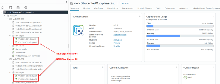
We have dedicated NSX edge clusters for each vSphere supervisor.
- VxDC01-C01-EC01: This is the dedicated edge cluster for vSphere supervisor 1 and is co-located with the same vSphere cluster VxDC01-C01.
- VxDC01-C02-EC01: This is the dedicated edge cluster for vSphere supervisor 2 and is co-located with the same vSphere cluster VxDC01-C02.
Both edge clusters are prepared on respective overlay transport zones as their vSphere supervisor clusters.

We have dedicated T0 Provider gateways for each vSphere supervisor. The necessary T0 configurations including BGP peering, route redistribution, route aggregation etc are already in place. Please check out the previous articles to learn more on this configuration.

Unlike the previous topology, we have segments for AVI SE management and system DNS on each overlay transport zone for their respective vSphere supervisors, each up streamed to their respective T1 gateways. This is because each overlay transport zone maps as a separate cloud connector in AVI, and each cloud connector will require a management network on the respective overlay transport zone.

Each T1 gateway up streams to the respective T0 gateway

AVI walkthrough
As stated earlier, each NSX overlay transport zone maps as a separate cloud connector in AVI. As such, we have the below two cloud connectors:
- VxDC01-NSXMGR01-C01: for overlay transport zone TZ-Overlay-VxDC01-C01
- VxDC01-NSXMGR01-C02: for overlay transport zone TZ-Overlay-VxDC01-C02

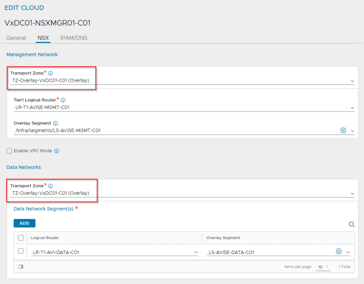
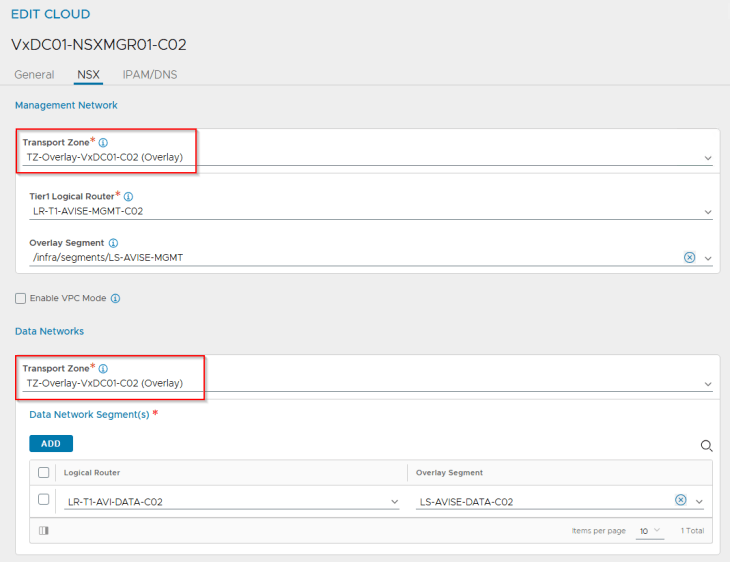
Each cloud connector is updated with the respective template SE group based on the desired AVI SE placement settings.
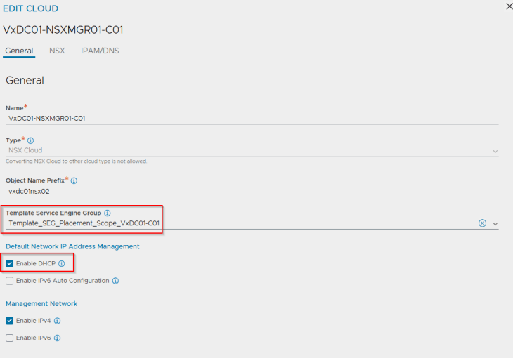
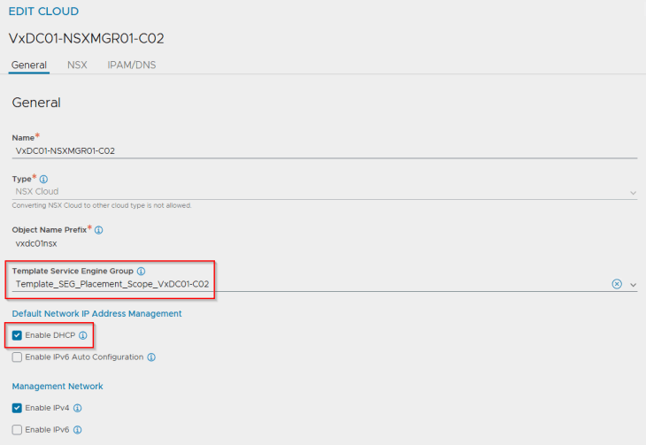
Each cloud connector has separate IPAM and DNS profiles attached. These placeholder IPAM profiles doesn’t have any networks added, and will be dynamically updated as and when the vSphere supervisors and vSphere namespaces are configured.
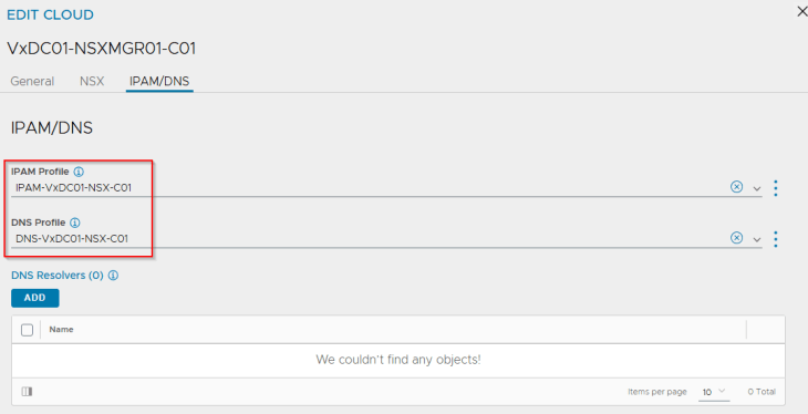
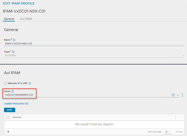
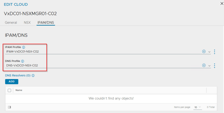
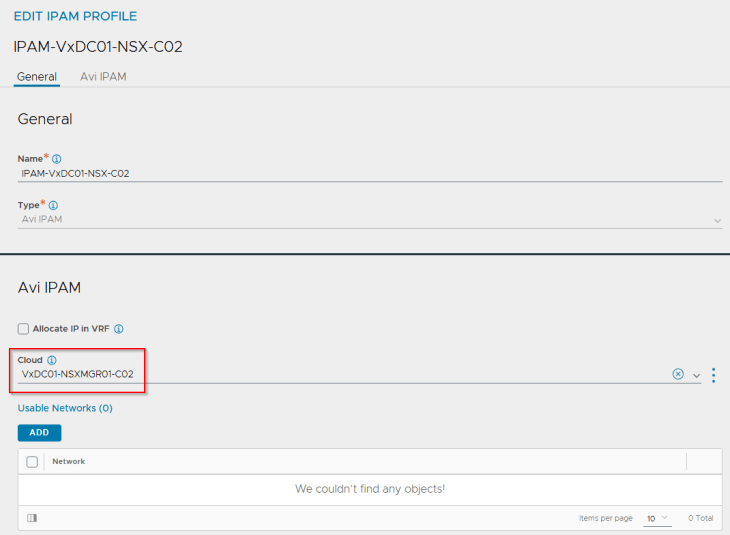
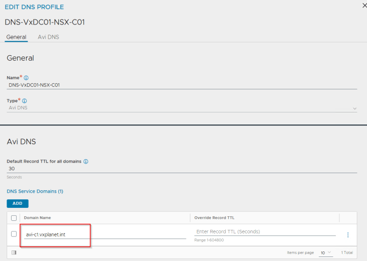
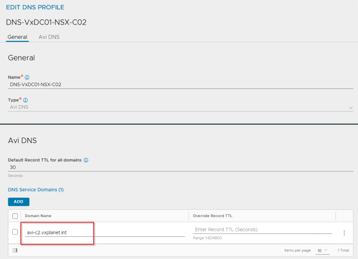
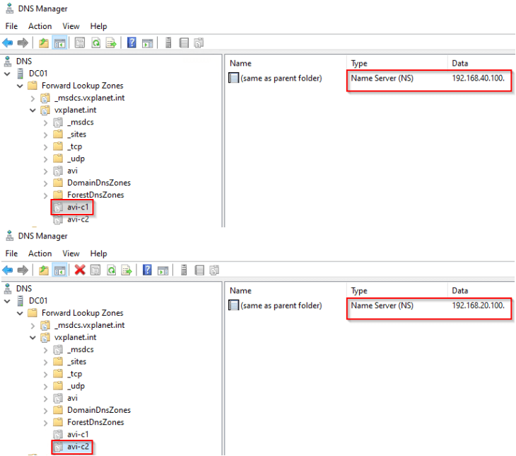
Separate DNS sub-domains are configured for each cloud connector, that will be used by L7 Ingress on the TKG service clusters. Additional sub-domains can be added independently, if needed.
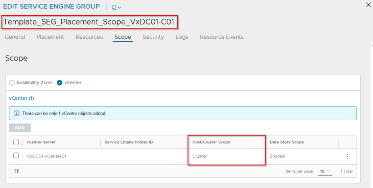
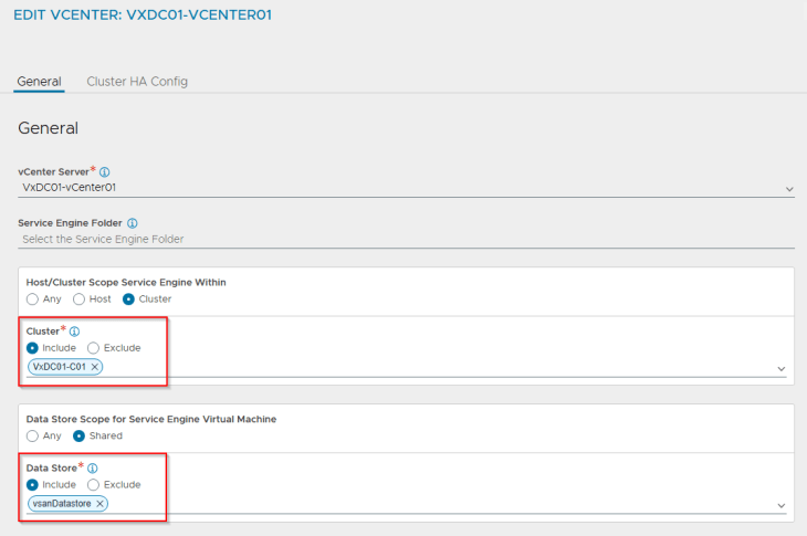
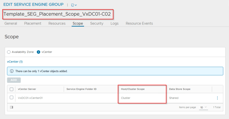
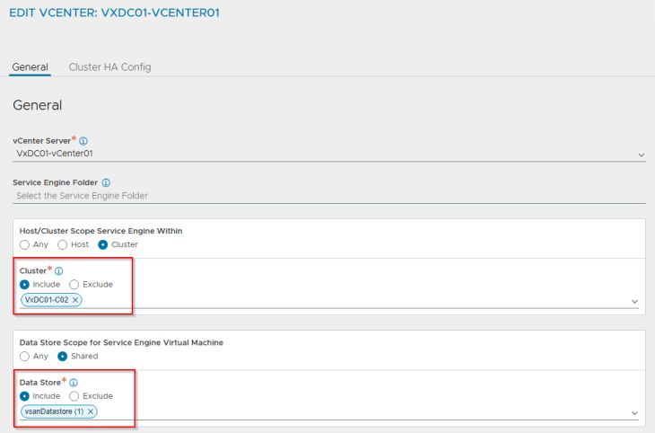
We have two SE Group templates created, each under the respective cloud connector – one for vSphere supervisor 1 and the other for vSphere supervisor 2. The reason for this is to provide different placement settings for the service engines in vCenter, so that they are co-located on the respective vSphere clusters similar to how the NSX edge nodes are placed.
- SEs for vSphere supervisor 1 will be co-located on the vSphere cluster VxDC01-C01, and
- SEs for vSphere supervisor 2 will be co-located on the vSphere cluster VxDC01-C02


Below is the placement settings for the SE Group template for vSphere supervisor 1 under cloud connector “VxDC01-NSXMGR01-C01”:
and below is the placement settings for the SE Group template for vSphere supervisor 2 under cloud connector “VxDC01-NSXMGR01-C02”:
We have two system DNS virtual services configured under each cloud connector. This is required for L7 Ingress on the TKG service clusters (Optional).

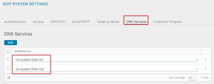
and finally, we have DNS delegations configured on the upstream DNS servers for the DNS sub-domains that the AVI DNS virtual services are authoritative for:
Activating vSphere Supervisor 1 (VxDC01-C01)
Now let’s activate vSphere supervisor on VxDC01-C01.
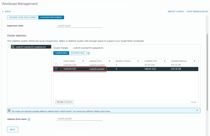
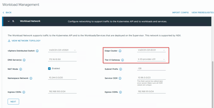
We will select the edge cluster “VxDC01-C01-EC01” and the T0 gateway “lr-t0-provider-c01” that is meant for this supervisor.
Success!!! vSphere supervisor 1 activation workflow has succeeded.

Activating vSphere Supervisor 2 (VxDC01-C02)
Let’s repeat the same workflow for supervisor 2 activation.
Note: As the vSphere supervisors use different AVI cloud connectors, it’s also possible to run the activation workflow for both supervisors together to save time.
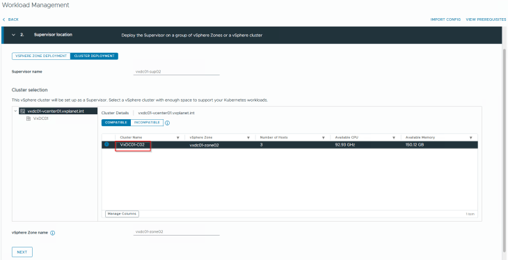
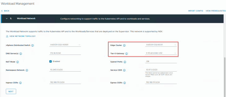
We will select the edge cluster “VxDC01-C02-EC01” and the T0 gateway “lr-t0-provider-c02” that is meant for this supervisor.
and finally, we should have both the supervisors up and running.

Reviewing NSX objects
Now let’s review the NSX objects that are created by the workflows.
As discussed in previous chapters, dedicated T1 gateways are created for vSphere supervisor and vSphere namespaces. These T1 gateways are up streamed to their respective T0 gateways, as shown below:

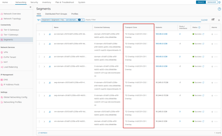
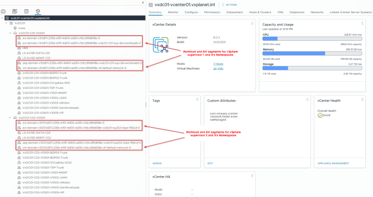
The supervisor workload segments, namespace segments, TKG service cluster segments and the AVI data segments for both vSphere supervisors are created under their respective overlay transport zone, that has a span only within the boundary of the vSphere cluster. Hence these networks are not stretched or visible to the other supervisor cluster and we have data plane isolation for the vSphere supervisor networks.
Reviewing AVI objects
Now let’s review the AVI objects that are created by the workflows.
The T1 gateways and AVI data segments of the supervisors are added by the workflows to their respective cloud connectors as data networks.
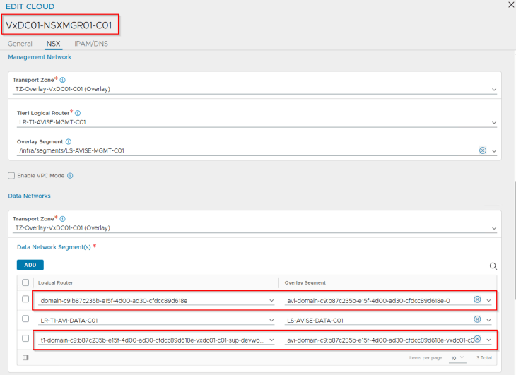
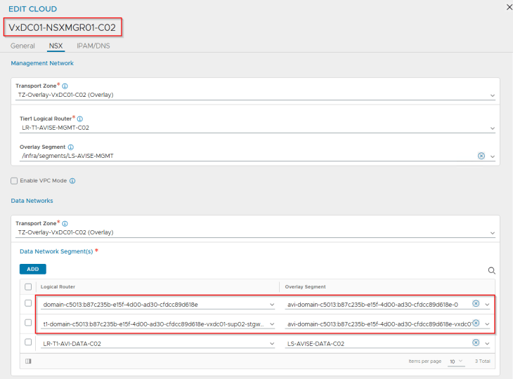
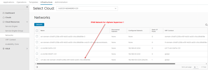
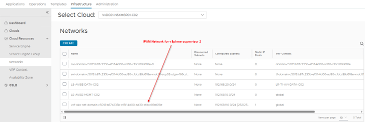
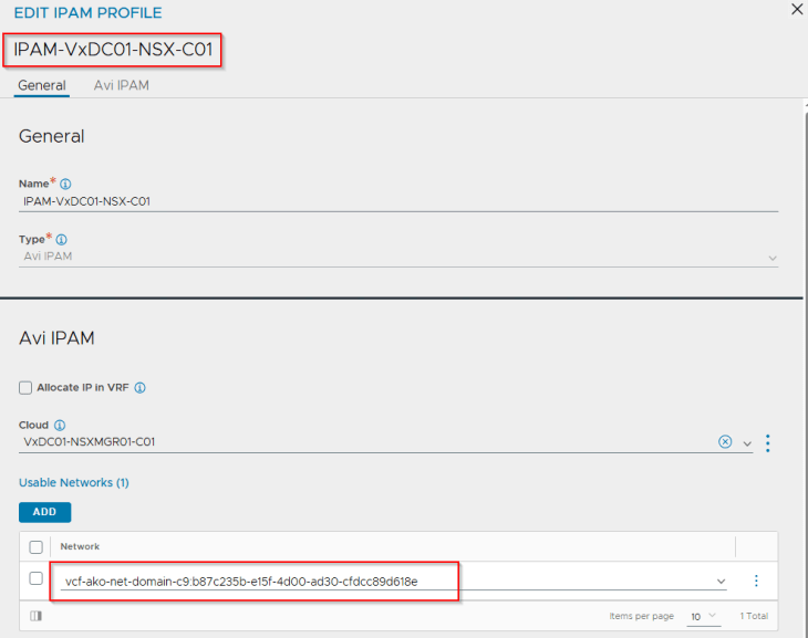
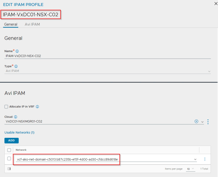
The IPAM networks are dynamically added to the respective IPAM profiles of the NSX cloud connector.
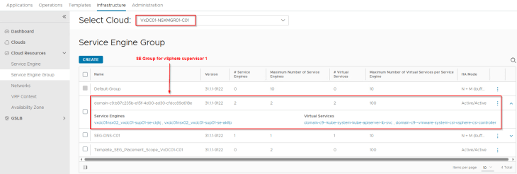
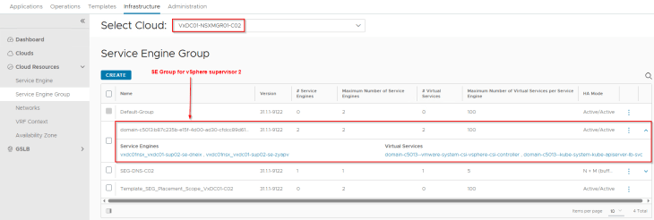
One SE Group is created under each cloud connector for the vSphere supervisor, which is a clone of the template SE group specified under the cloud connector.
Let’s review the vCenter inventory and confirm that the SEs are placed as expected.
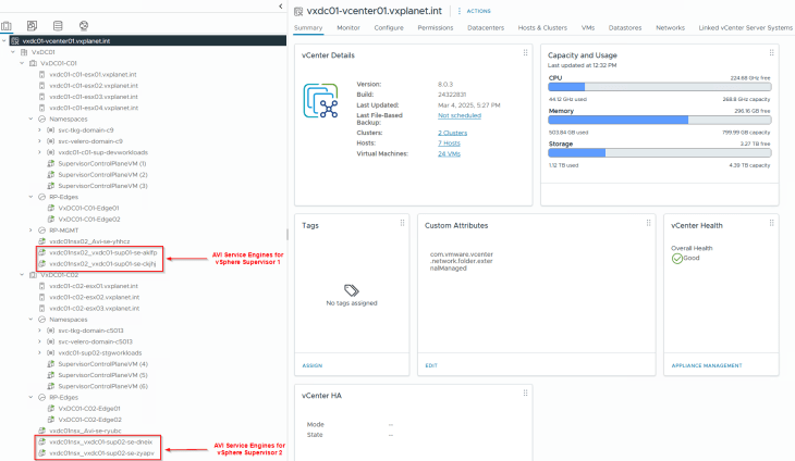
and finally, let’s confirm the status of supervisor control plane VIPs in AVI.

Excellent, we have now reached the end of this article. The next and the final chapter of this blog series is around the topology of a three-zone supervisor, and I would need to scale out my home lab again with an additional vSphere cluster. The resources are pretty much limited, and I need to squeeze the resources further to make room for this deployment, I hope to be back soon.
Stay tuned!!!
I hope this article was informative. Thanks for reading.

Continue reading? Here are the other chapters of this series:
Part 1: Architecture and Topologies
https://vxplanet.com/2025/04/16/vsphere-supervisor-networking-with-nsx-and-avi-part-1-architecture-and-topologies/
Part 2: Environment Build and Walkthrough
https://vxplanet.com/2025/04/17/vsphere-supervisor-networking-with-nsx-and-avi-part-2-environment-build-and-walkthrough/
Part 3: AVI onboarding and Supervisor activation
https://vxplanet.com/2025/04/24/vsphere-supervisor-networking-with-nsx-and-avi-part-3-avi-onboarding-and-supervisor-activation/
Part 4: vSphere namespace with network inheritance
https://vxplanet.com/2025/05/15/vsphere-supervisor-networking-with-nsx-and-avi-part-4-vsphere-namespace-with-network-inheritance/
Part 5: vSphere namespace with custom Ingress and Egress network
https://vxplanet.com/2025/05/16/vsphere-supervisor-networking-with-nsx-and-avi-part-5-vsphere-namespace-with-custom-ingress-and-egress-network/
Part 6: vSphere namespace with dedicated T0 gateways
https://vxplanet.com/2025/05/16/vsphere-supervisor-networking-with-nsx-and-avi-part-6-vsphere-namespace-with-dedicated-t0-gateway/
Part 7: vSphere namespace with dedicated VRF gateways
https://vxplanet.com/2025/05/20/vsphere-supervisor-networking-with-nsx-and-avi-part-7-vsphere-namespace-with-dedicated-t0-vrf-gateway/
Part 8: Multiple supervisors on shared NSX transport zone
https://vxplanet.com/2025/06/08/vsphere-supervisor-networking-with-nsx-and-avi-part-8-multiple-supervisors-on-shared-nsx-transport-zone/
Part 10: Zonal supervisor with AVI availability zones
https://vxplanet.com/2025/06/12/vsphere-supervisor-networking-with-nsx-and-avi-part-10-zonal-supervisor-with-avi-availability-zones/


