Welcome back!!! We are at Part 3 of the blog series on vSphere Supervisor networking with NSX and AVI. In the previous two articles, we discussed the architecture of vSphere supervisor and the different topologies of vSphere namespaces, multiple supervisor clusters, zonal supervisors and the current environment build details to activate the vSphere supervisor (starting with a single-zone supervisor). We will scale out the environment with additional vSphere clusters as we progress.
In this article, we will discuss the AVI onboarding workflow with NSX, activate vSphere supervisor, review the NSX and AVI objects that are created and revisit the supervisor topology that we discussed in Part 1.
If you missed the previous articles of this series, please check them out below:
Part 1: Architecture and Topologies
https://vxplanet.com/2025/04/16/vsphere-supervisor-networking-with-nsx-and-avi-part-1-architecture-and-topologies/
Part 2: Environment Build and Walkthrough
https://vxplanet.com/2025/04/17/vsphere-supervisor-networking-with-nsx-and-avi-part-2-environment-build-and-walkthrough/
Let’s get started:
AVI onboarding workflow
AVI onboarding workflow is currently a 1:1 mapping with the NSX manager, meaning one AVI Load Balancer cluster for each NSX Manager cluster.
AVI onboarding to NSX is done via API, and this process will set AVI as the enforcement point in NSX so that NSX will use AVI as the LB instead of native-LB. This will be a PUT operation against the ‘/api/v1/infra/alb-onboarding-workflow’ endpoint with the below json body, let’s use Postman to do this:
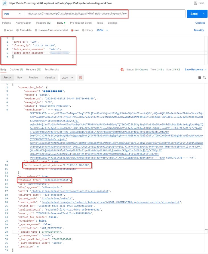
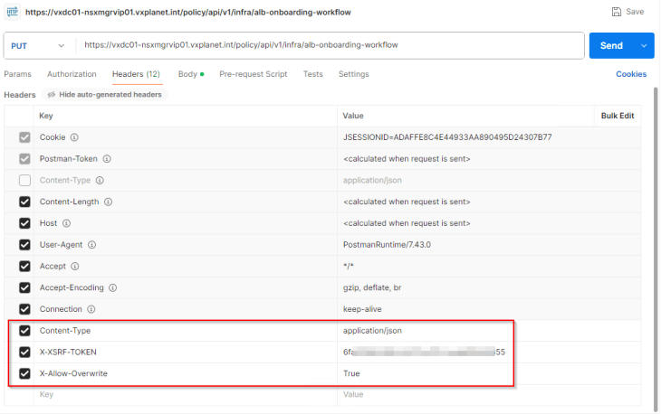
The request header should have ‘X-Allow-Overwrite’ key set to True.
To confirm that AVI has been successfully added as an enforcement point in NSX, let’s perform a GET request to the ‘/api/v1/infra/sites/default/enforcement-points/alb-endpoint’ endpoint.
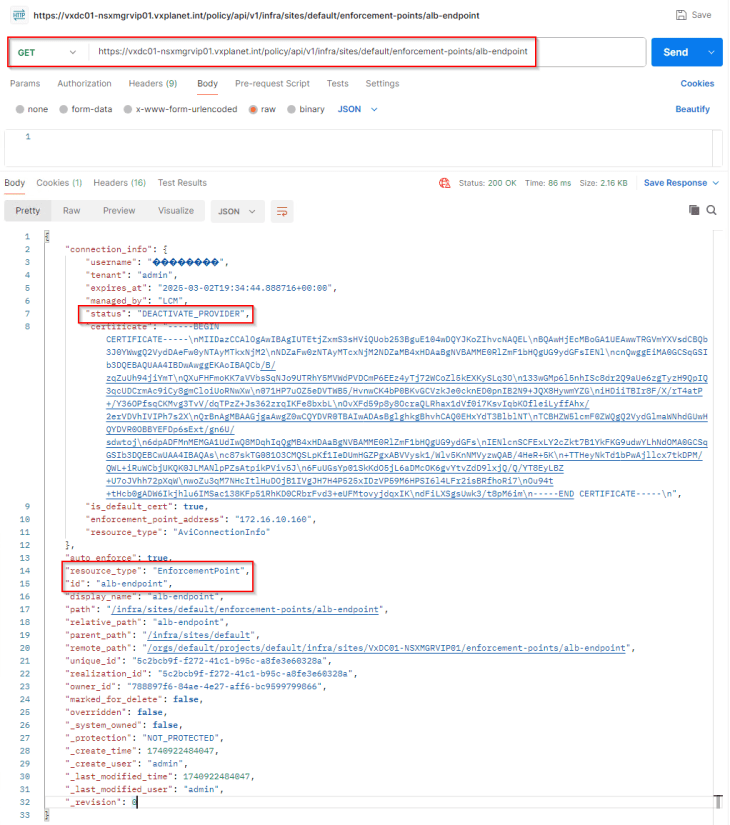
The key-value pair ‘status’ : ‘DEACTIVATE_PROVIDER” confirms that the operation is successful, and that AVI will be leveraged for load balancer services.
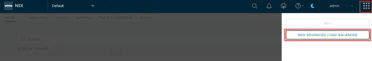
We will also see NSX Advanced Load Balancer (legacy name though) listed under the NSX App Switcher.
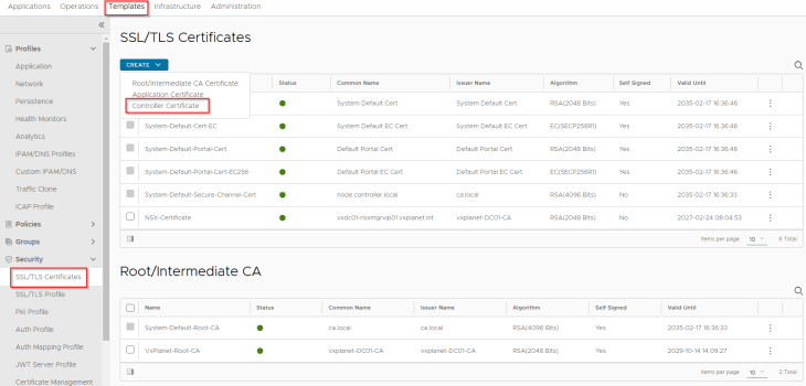
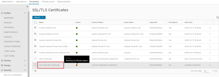
Replacing default AVI Portal Certificate
The default AVI portal certificate is self-signed without a SAN field, which cannot be used for vSphere supervisor integration. We will replace this with an internal CA signed certificate.
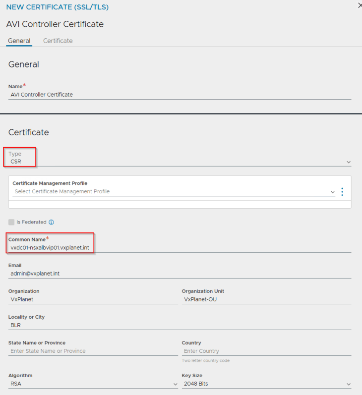
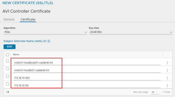
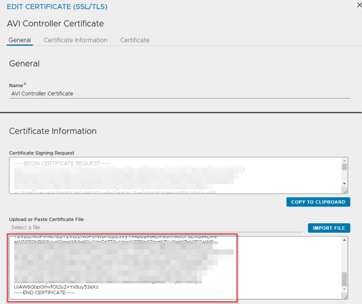
Let’s create the CSR from AVI console with the SAN fields updated with AVI VIP and individual node FQDNs.
We will present the CSR to the internal CA ‘VxPlanet-DC01-CA’ and upload the certificate as a chain in AVI.
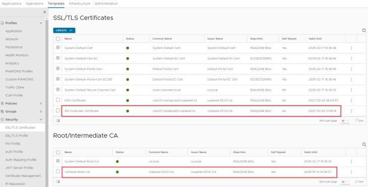
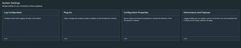
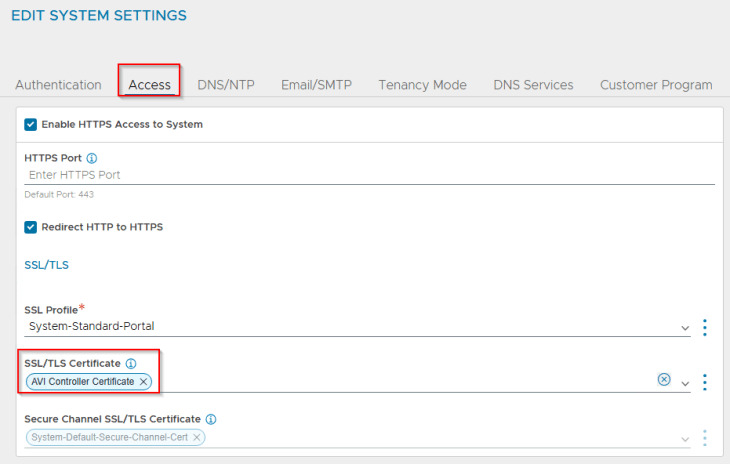
and finally we will switch to the new CA-signed certificate under System-Settings.
Adding the private CA root / intermediate certificate to the Java certificate trust store in NSX
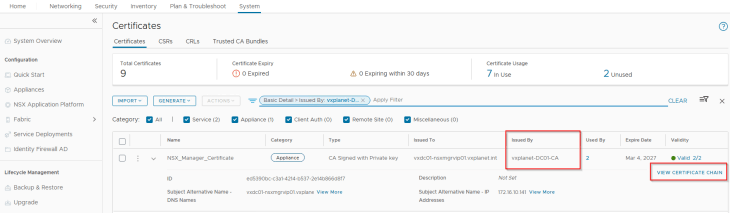
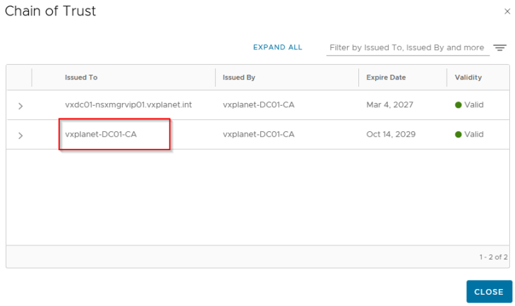
As discussed in Part 2, NSX manager is using an internal CA signed certificate (for MGMT_Cluster and Rest API) and the internal root CA certificate is available in the NSX trust store but not in the Java trust store.
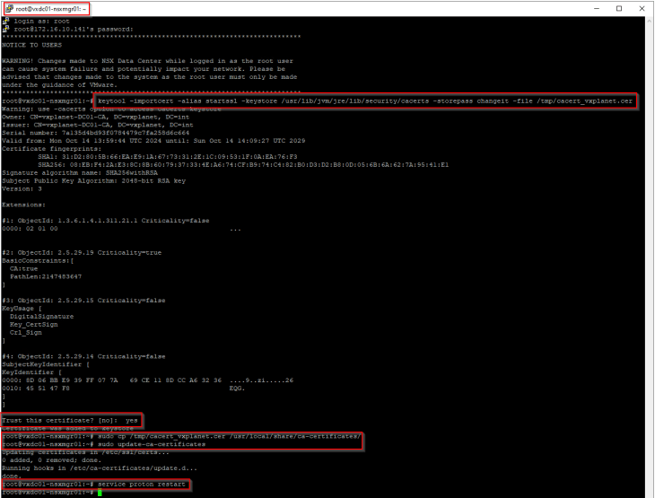
As per the official documentation, Java SDK is used to establish communication between NCP and AVI Controller cluster, hence we need to import the internal root CA certificate (and any intermediate certs, if any) to the Java certificate trust store in NSX.
https://techdocs.broadcom.com/us/en/vmware-cis/vsphere/vsphere-supervisor/8-0/installing-and-configuring-vsphere-supervisor/troubleshooting-networking/troubleshooting-nsx-advanced-load-balancer.html
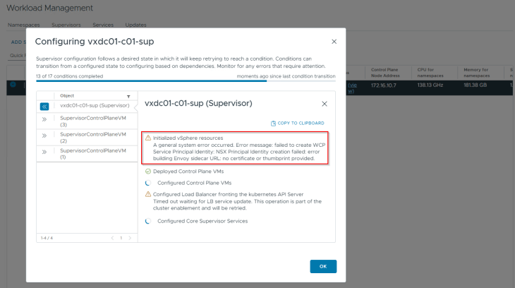
If we miss this step, vSphere supervisor activation will most likely fail with the below error:
Activating vSphere Supervisor
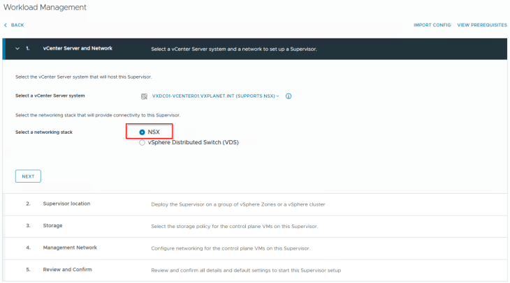
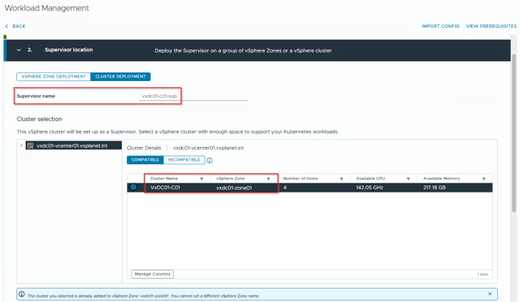
Now that we have all the pre-requisites in place, it’s time to activate the vSphere supervisor. This will be a single-zone supervisor with NSX as the networking stack.
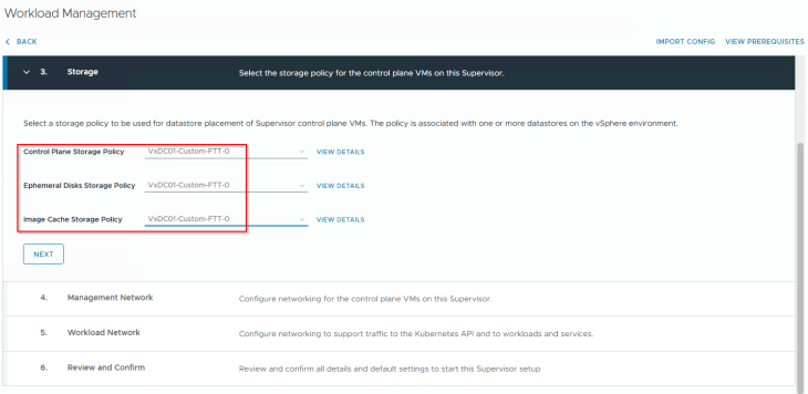
We will choose the custom vSAN storage policy that we created in Part 2 for the supervisor control plane VMs, ephemeral disks and image disks.
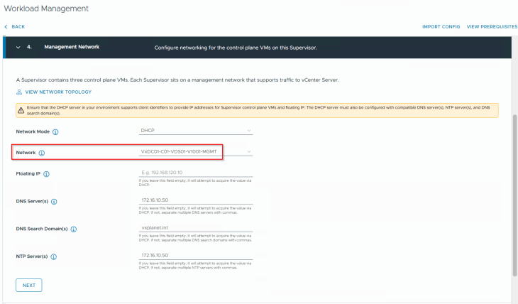
Each supervisor control plane VM is dual-nic’ed with one nic attaching to vCenter DVPG on the management port group (VxDC01-C01-VDS01-V1001-MGMT) and the other nic on the overlay NSX workload segment. Since we have DHCP enabled on the management VLAN, we will choose DHCP as the network mode for the supervisor control plane VMs.
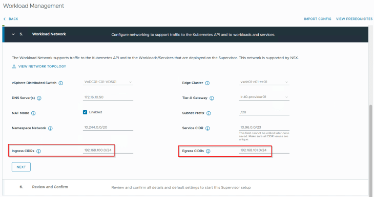
We will choose the default namespace network 10.244.0.0/20 for the vSphere supervisor. The field for ‘Subnet Prefix’ defines how the workload and TKG service cluster networks will be carved out from the namespace CIDR. A value of /28 means blocks of /28 networks will be used for the workload networks (but we can override this with a custom value under the vSphere namespaces).
This namespace network can be either routable or behind NSX T1 NAT. For this deployment, we will choose NAT.
Ingress and Egress CIDRs come from a unique network that is not used in the infrastructure. They are assigned to AVI VIPs and SNAT policies respectively and are advertised to the physical fabrics by the T0 gateway. If NAT mode is not enabled, Egress CIDR is not required as we don’t need SNAT.
The T0 gateway will be the Provider T0 that we discussed in the previous article. This is where the supervisor T1’s and vSphere namespace T1’s attach to.
Edge cluster specified in the workflow will host the supervisor and namespace T1 gateways that are created by the workflow. This can be either a dedicated edge cluster for the T1s or a shared edge cluster with the T0 gateway. For this deployment, we will use a shared edge cluster model.
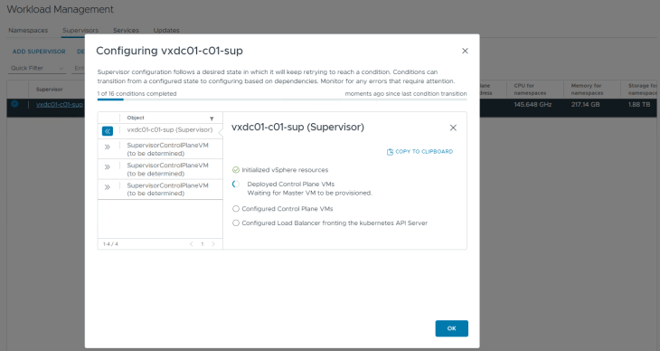
We will go with a small footprint for the supervisor control plane VMs (as our objective is for the blog article). Optionally, we could specify a DNS name for the kube API VIP. Clicking on Finish will start the vSphere supervisor activation and convert the vSphere cluster to a vSphere supervisor cluster.
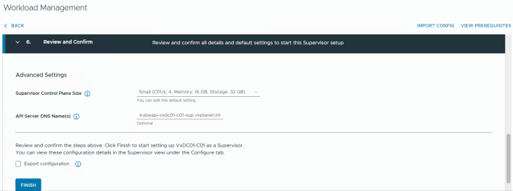
This will take a while to complete, let’s break for a quick coffee and once we are back, this should be completed.
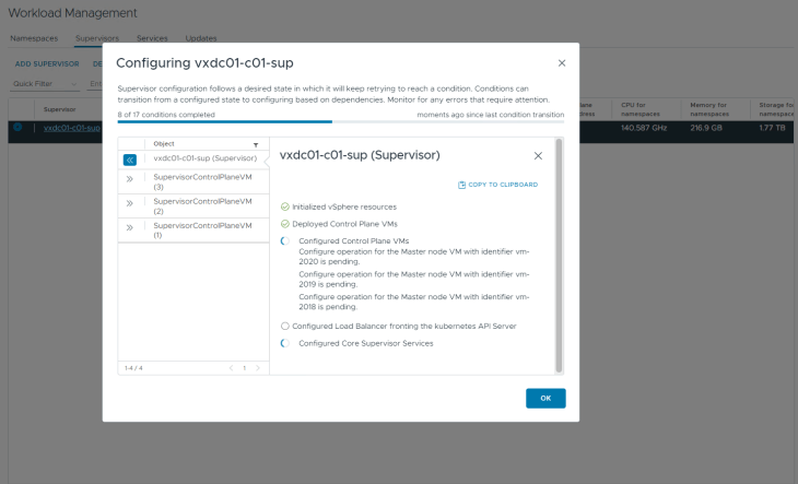
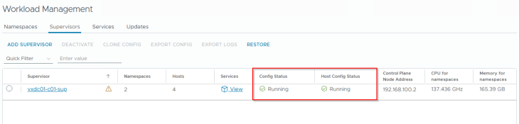
Okay, I am back, and we have the vSphere supervisor successfully activated, up and running. We have a VIP from the Ingress CIDR front ending the supervisor Kube API (192.168.100.2). Remember we specified a DNS name for the kube API VIP in the workflow, it’s time to add a DNS record for this.
Let’s login to the vSphere supervisor.
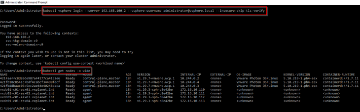
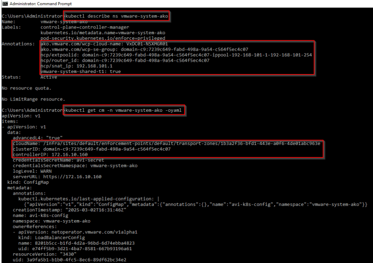
If we review the ‘vmware-system-ako’ system namespace, we should see annotations with the details of AVI cloud connector, AVI SE Group, SNAT IP Pool and the T1 gateway of supervisor. The AKO config map should also show the details of the AVI controller cluster and the cloud connector. This shows that the vSphere supervisor has been initialized properly with AVI (and not native NSX LB) as the load balancer.
Reviewing NSX objects
Now let’s review the NSX objects that are created by the workflow.
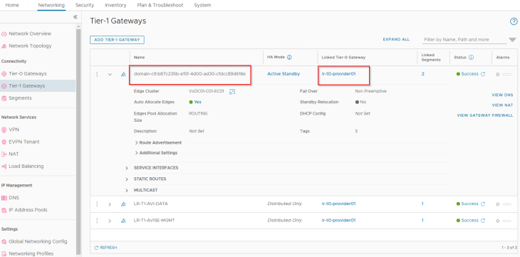
As discussed in Part 1 – Architecture and Topologies, a dedicated T1 gateway is created for the vSphere supervisor up streamed to the provider T0 gateway.
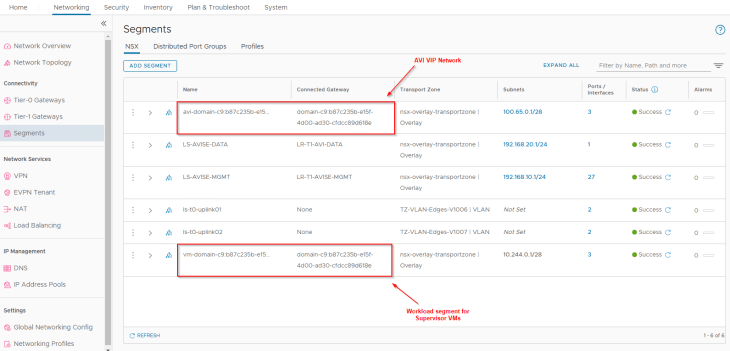
Two default segments are created, both attached to the supervisor T1 gateway:
- Workload network : This is where the supervisor control plane VMs attach to. This network is carved out from the namespace network specified in the workflow.
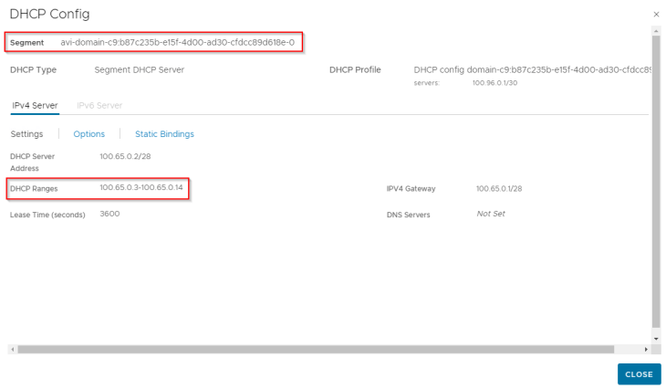
- AVI data segment : This is where the AVI data interfaces hosting the control plane VIPs attach to. This is a non-routable subnet on the CGNAT range and has DHCP enabled.
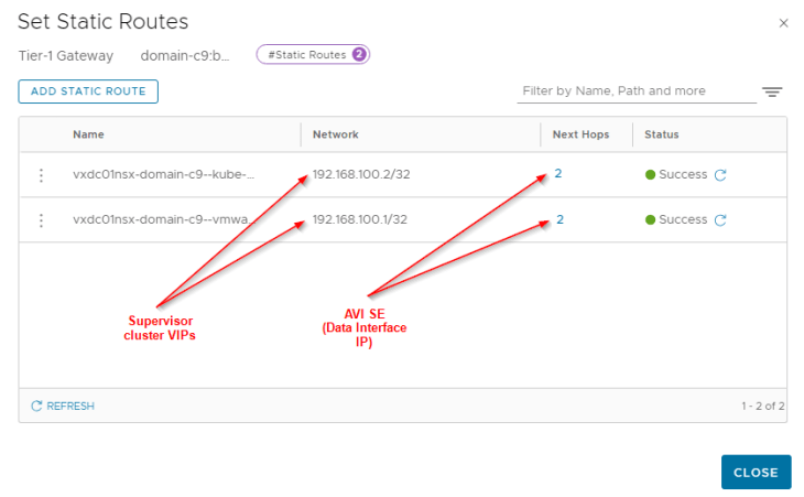
For each VIP created in AVI, a static route is programmed under the T1 gateway with next hop pointing to the data interface of AVI service engines.
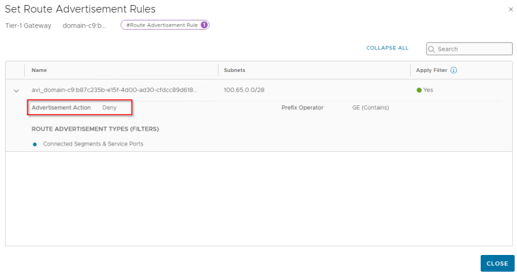
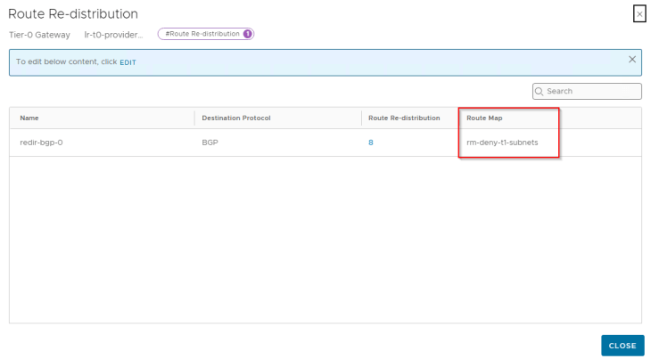
Since we enabled NAT mode for the workload network, a route-map is added to BGP route-redistribution policy to prevent namespace networks from getting advertised to upstream physical fabrics.
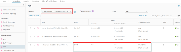
We also have an SNAT rule under the T1 gateway for outbound communication. Note that east-west communication between supervisor and vSphere namespaces will always happen with No-SNAT.
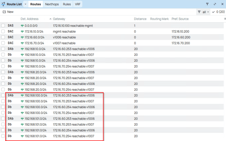
and finally, checking the routing table on the upstream physical fabrics, we see Ingress and Egress networks advertised from the T0 gateway. Because we enabled route aggregation on the T0 gateway to advertise only the summary route, we won’t see the more specific host routes (/32) in the physical fabrics, but just the summary route (/24).
Reviewing AVI objects
Now let’s review the AVI objects that are created by the workflow.
The T1 gateway created for the vSphere supervisor and the AVI data segment will be added by the workflow as data networks to the AVI cloud connector that we configured in Part 2.
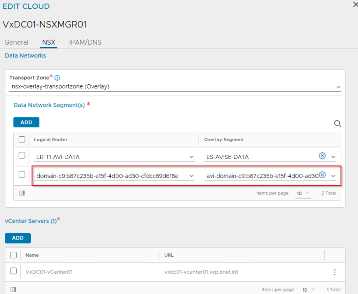
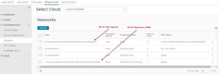
We will see two networks:
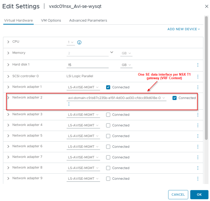
- AVI data network – As discussed previously, AVI SEs will work in a single arm mode under the NSX cloud connector. One SE interface will be consumed for each T1 gateway in the cloud connector and this interface will attach to the respective data network under the T1 gateway. DHCP is enabled on this data network (through segment DHCP in NSX)
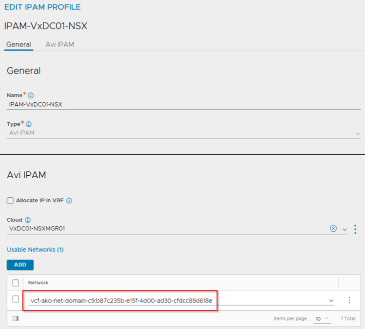
- VIP network – This will be added to the IPAM profile for dynamic IP allocation for L4 and L7 services. The VIP network will be the Ingress CIDR that was specified during the supervisor activation workflow.
If we review the IPAM profile attached to the NSX cloud connector, we see that the VIP network has been added under usable networks.
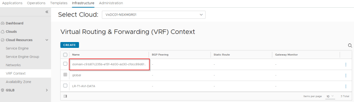
The Supervisor T1 gateway added under the NSX cloud connector will be mapped as a VRF context. We don’t need to add a default route for this VRF context because DHCP is already enabled on the AVI data network which can provide the default gateway information to the SEs.
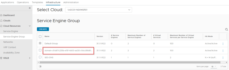
Since we didn’t have a template SE Group specified in the NSX cloud connector, a new SE Group has been created for the vSphere supervisor which is a cloned configuration of the “Default-Group”. In Part 2, we already prepared this “Default-Group” with the desired HA mode, sizing and placement details.
Reviewing the SE interface details, we see that one interface is consumed for the T1 gateway (supervisor T1 gateway). Additional interfaces will be consumed as and when vSphere namespaces are created.
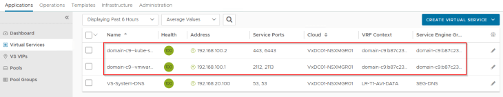
and finally, we see the supervisor control plane VIPs up and running in AVI (under the NSX cloud connector and on the supervisor T1 VRF Context)
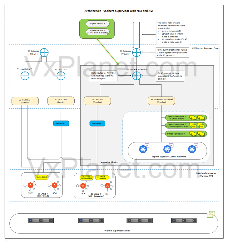
Revisiting the vSphere Supervisor Topology
Now that we reviewed the NSX and AVI objects, we could confirm that the deployed vSphere supervisor topology aligns to what we discussed in Part 1.
Let’s conclude for now and we will meet in Part 4 to discuss vSphere namespace topologies that inherit network settings from the supervisor. Stay tuned!!!
I hope the article was informative. Thanks for reading.

Continue reading? Here are the other parts of this series:
Part 1: Architecture and Topologies
https://vxplanet.com/2025/04/16/vsphere-supervisor-networking-with-nsx-and-avi-part-1-architecture-and-topologies/
Part 2: Environment Build and Walkthrough
https://vxplanet.com/2025/04/17/vsphere-supervisor-networking-with-nsx-and-avi-part-2-environment-build-and-walkthrough/