Welcome back to Part 2 of our blog series on Distributed Malware Prevention & Sandboxing for VCF with VMware vDefend. In the previous chapter, we covered the architectural overview of Malware Prevention Service (MPS) and explored the sandboxing deployment options in VCF. In case you missed it, you can catch up here:
Part 1: Distributed Malware Prevention and Sandboxing Architecture
https://vxplanet.com/2026/09/20/distributed-malware-prevention-sandboxing-for-vcf-with-vmware-vdefend-part-1-architecture/
In this post, we will resume from where we left off and walk through the activation process and deployment of Malware Prevention Service (MPS) and the sandboxing environment for VCF. Let’s get started:
Current Environment and Platform Licensing
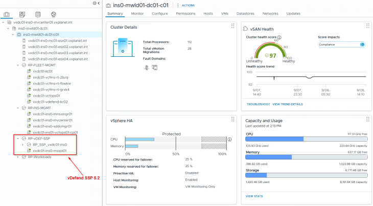
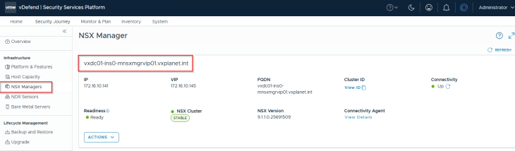
The current lab environment is a 4-node VCF 9.1.1 cluster deployed in a consolidated architecture (handling both management and compute roles). vDefend Security Services Platform 5.2 is already installed on this cluster, and the NSX manager instance has been successfully onboarded.
If you need guidance on SSP deployment, please check out my SSP series below. (Note: this series is based on version 5.1, but the deployment process remains exactly the same for 5.2)
vDefend Security Services Platform and Security Segmentation – Part 1 – Introduction
https://vxplanet.com/2025/12/18/vdefend-security-services-platform-and-security-segmentation-part-1-introduction/
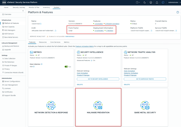
To support Malware Prevention Service, the SSP instance requires a minimum of 7 worker nodes deployed with at least a Large form factor.
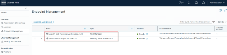
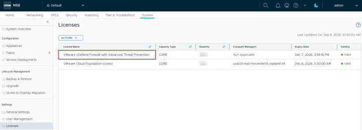
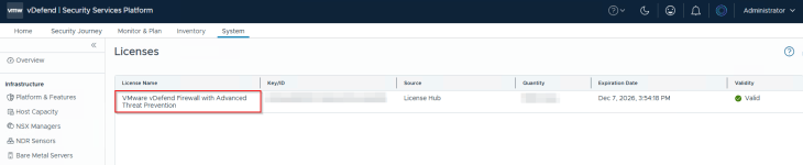
Finally, vDefend License Hub 2.0 is installed, with both the NSX Manager and the SSP instance added as license endpoints. Note that starting with version 5.2, the SSP instance must be licensed directly from the vDefend License Hub. For a deeper dive into License Hub 2.0 architecture and deployment, please check out my previous article below:
VMware vDefend License Hub 2.0 – Part 1 – Architecture and Deployment
https://vxplanet.com/2026/08/10/vmware-vdefend-license-hub-2-0-part-1-architecture-and-deployment/
Setting the SSP Connection Mode
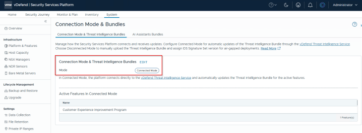
Because the lab environment has direct internet access, we will set the connection mode to Connected. In this mode, the SSP connects directly to the vDefend Threat Intelligence Service (vTIS) to automatically download the latest threat definition bundles.
Setting up the MPS Sandboxing cluster
Starting with SSP 5.2, MPS sandboxing environment is now completely on-premise, and require a vSphere cluster with atleast two ESXi hosts for HA adhering to one of the deployment topologies we discussed in the previous chapter. As such, the sandboxing cluster can be hosted:
- Under a separate workload domain managed by a dedicated vCenter server (Recommended)
- Co-located with the SSP Instance under the same vCenter server on the workload domain
- Co-located with the SSP Instance under the same vCenter server on the management domain
For this demonstration, I have set up a 2-node vSAN cluster for sandboxing within the same management domain.
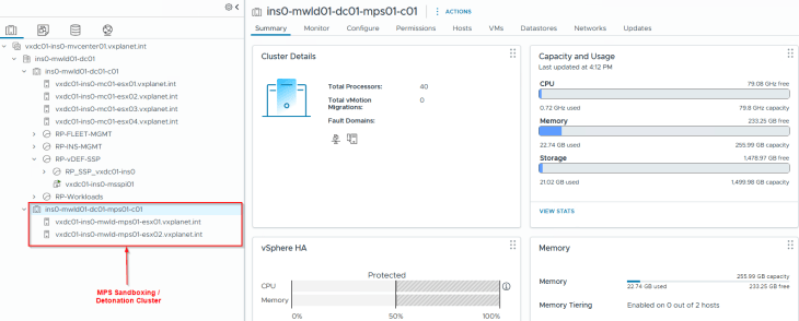
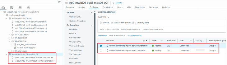
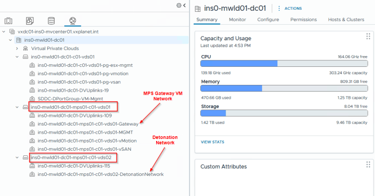
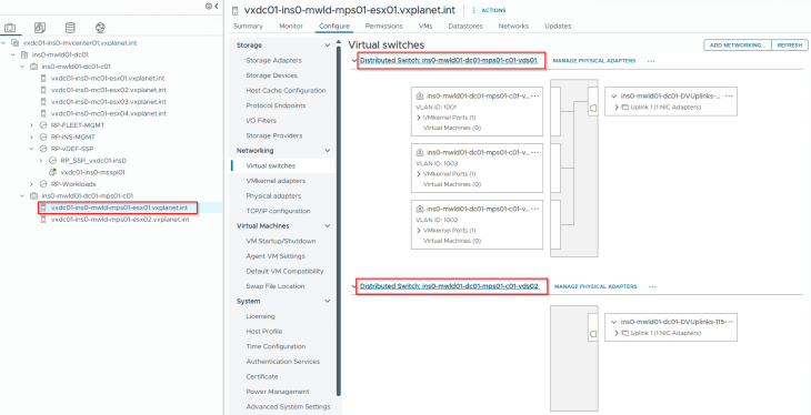
This vSphere cluster is configured with two VDS’s
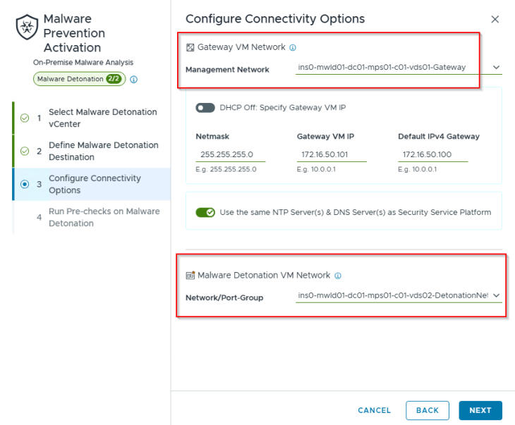
- ins0-mwld01-dc01-mps01-c01-vds01: This VDS handles the host management and infrastructure traffic, including the management network for the Gateway VM.
- ins0-mwld01-dc01-mps01-c01-vds02: This VDS is on an isolated network and exclusively hosts the traffic for Detonation VMs.
The sandboxing cluster has specific prerequisites regarding cluster configuration. vSphere DRS must be enabled with Automation Level set to Manual and vSphere HA must be turned OFF.
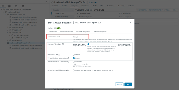
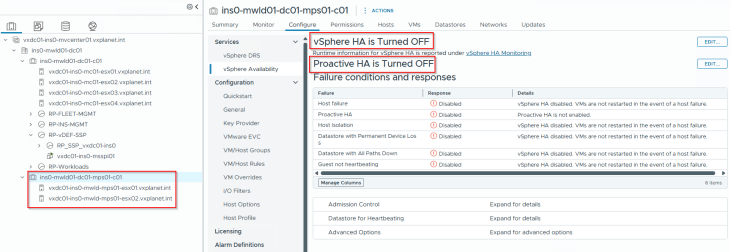
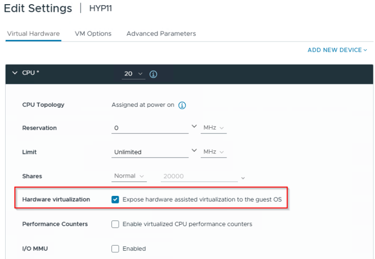
Note for Home Labs: If you are deploying the sandboxing cluster in a nested ESXi environment, ensure that Hardware Assisted Virtualization is set to Enabled on the nested host VMs as shown below:
Extending Minio Data Storage
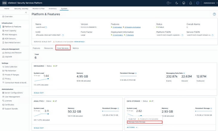
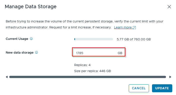
According to the official prerequisites documentation, a minimum of 1TB of available storage capacity is required on the MinIO cluster running in SSP. This space is used for the long-term storage of verdict analysis files and other detonation artifacts. Please check out the official link below to ensure all prerequisites are met:
https://techdocs.broadcom.com/us/en/vmware-security-load-balancing/vdefend/security-services-platform/5-2/malware-prevention/preparing-the-data-center-for-malware-prevention/prerequisites-and-system-requirements-for-malware-prevention-service.html
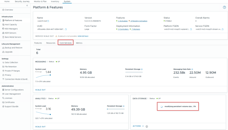
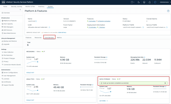
Let’s navigate to System -> Platform & Features -> Core Services -> Data Storage and increase the storage capacity accordingly.
Downloading the Sandbox Files
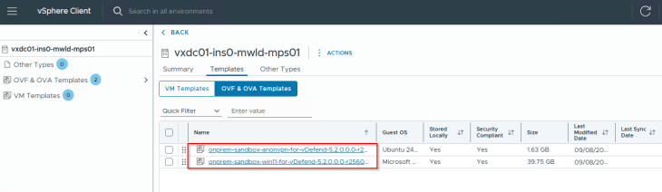
Log in to the Broadcom Support Portal and download the OVA templates for the Sandbox VM and the Gateway VM. (Note: The Gateway VM template is not required if MPS is deployed in Disconnected mode).
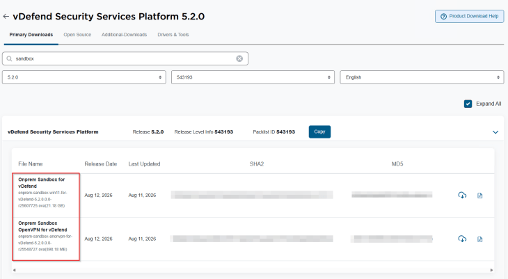
Upload these templates to the vCenter content library. Gateway VM and the Detonation VMs will be provisioned from these templates as we activate Malware Prevention Service in the next step.
Activating Malware Prevention Service – Step 1 – Static Analysis
Activating Malware Prevention Service is a two-step process:
- Step 1: Activate Static Analysis
- Step 2: Activate on-premise Sandboxing
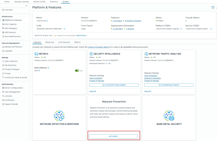
Let’s navigate to System -> Platform & Features -> Features -> Malware Prevention and activate the tile.
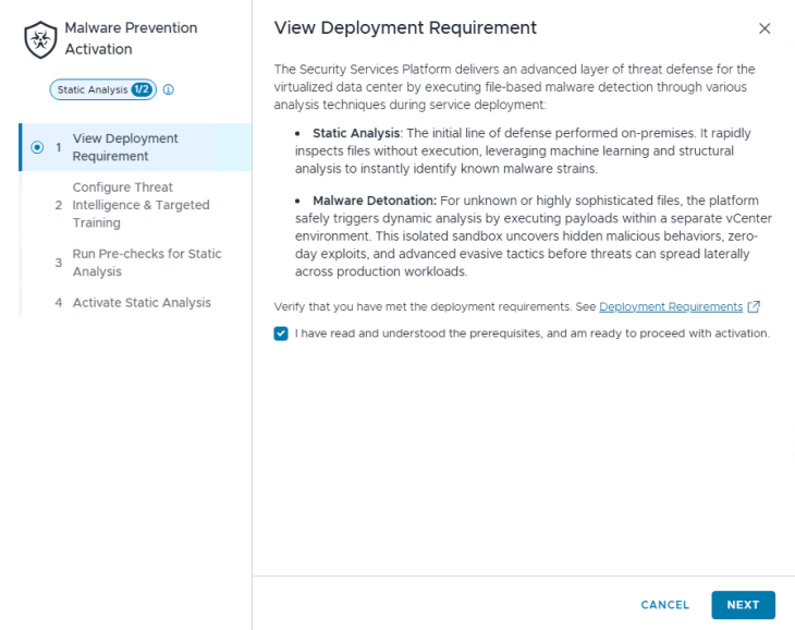
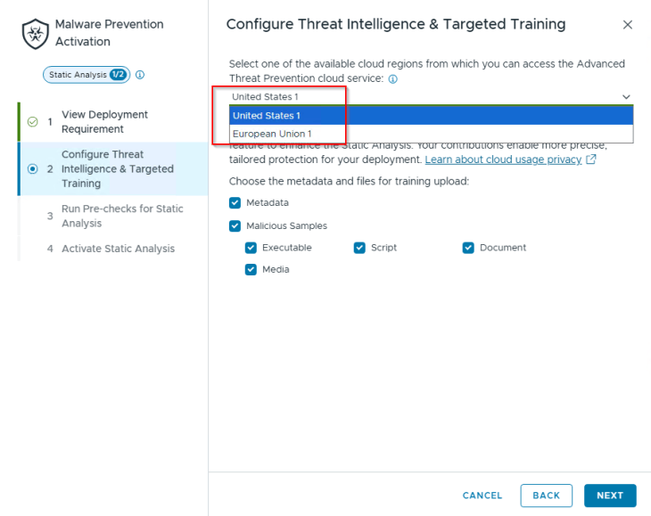
Since we are activating MPS in Connected mode, we need to choose a cloud region to access the Advanced Threat prevention service. This region is used to establish the AutoVPN connection and, optionally, to share analysis metadata for threat-training purposes.
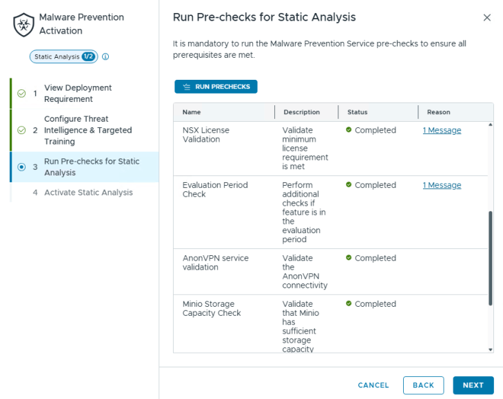
We will wait for the pre-requisites checks to complete and then start static analysis activation.
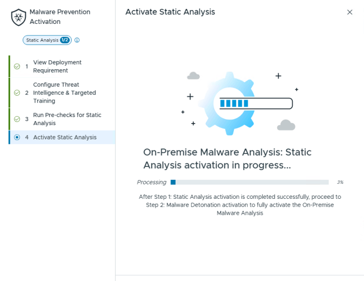
Once static analysis is successfully activated, proceed to Step 2 for activating the sandboxing environment.
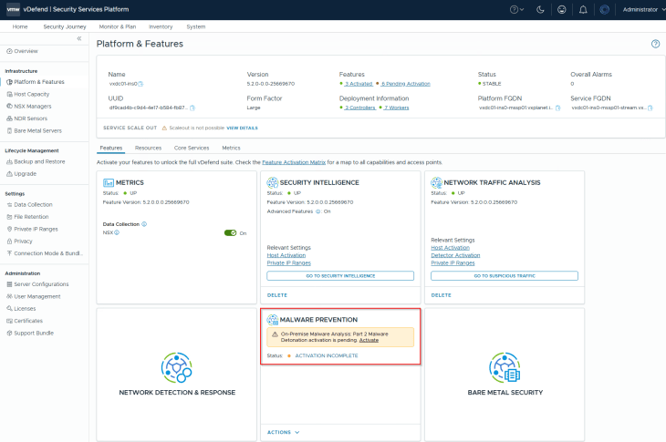
Activating Malware Prevention Service – Step 2 – Sandboxing
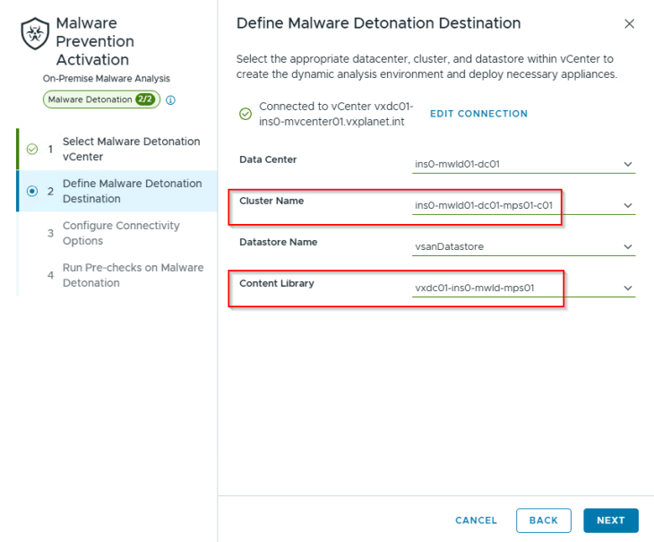
Let’s connect to the vCenter server where the sandboxing vSphere cluster is hosted. In our case, it’s the same management cluster (consolidated architecture) where the SSP Instance is deployed.
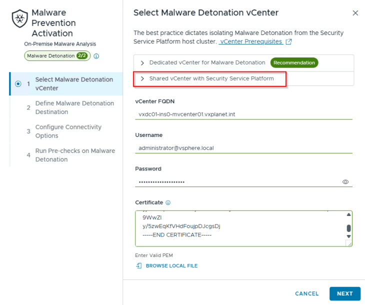
We will select the port groups for Gateway VM management and Detonation VM networking. Note that these port groups correspond to the separate VDSs we provisioned earlier.
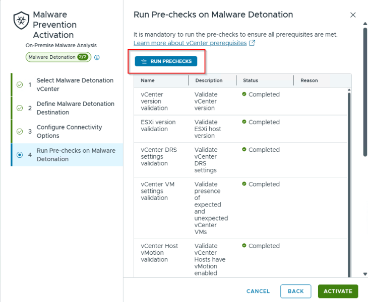
We will wait for the pre-requisites checks to complete and then start sandboxing activation.
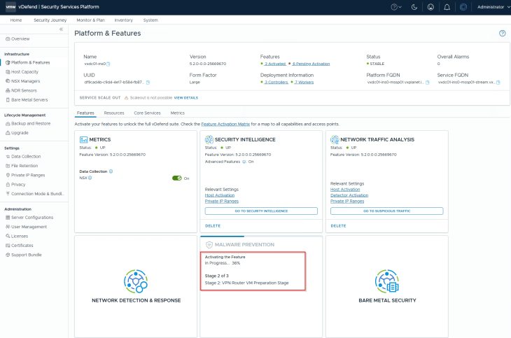
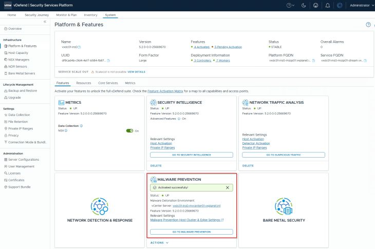
Once Sandboxing is activated, we will see that the Gateway VM and the Detonation Parent VMs have been deployed and provisioned. Whenever a sandboxing activity is initiated, the actual detonation VMs are created as instant clones from this parent VM.
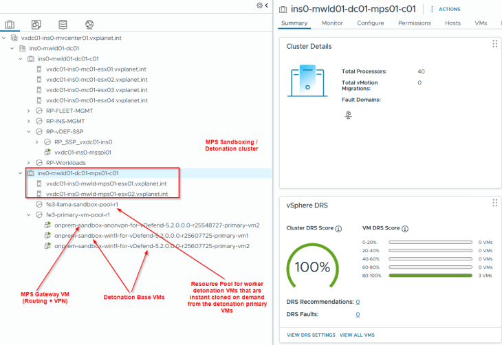
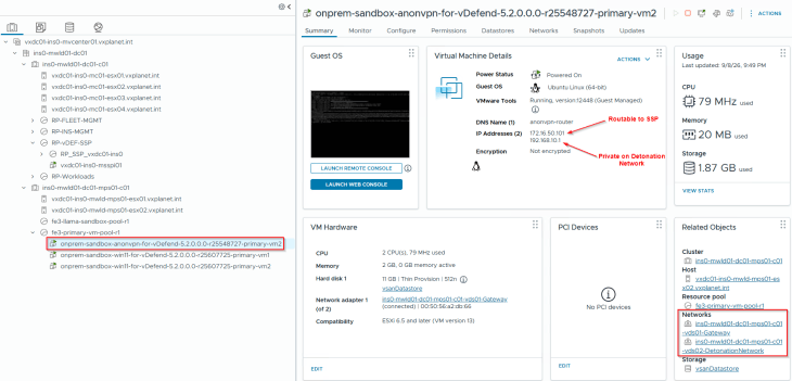
As discussed in the previous chapter, the Gateway VM is configured with two interfaces:
- One on the Gateway management subnet which is routable to SSP
- One on the isolated Detonation Network
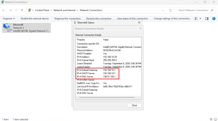
All of the instant clone detonation VMs will point to this Gateway VM as their default gateway.
Deploying SVMs for Distributed Malware Prevention
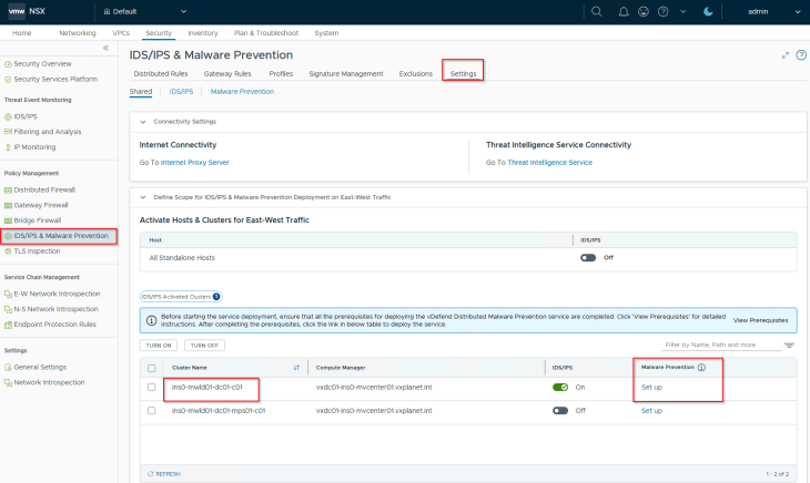
Now that the Malware Prevention Service is activated on SSP, the final step is to deploy the Service VMs (SVMs) to enable the Distributed Enforcement Point. This action is performed directly from the NSX Manager that is paired with the SSP instance.
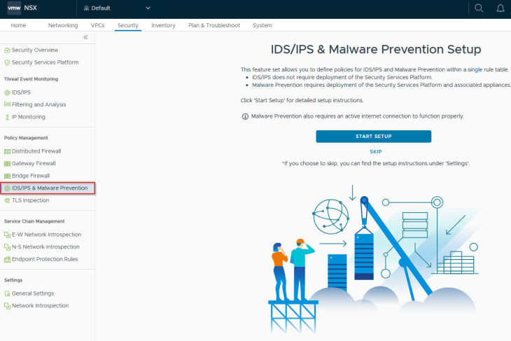
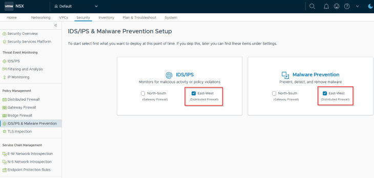
As we enable distributed MPS, we will also choose to activate IDPS on the workload clusters. This is optional, but recommended in order to correlate and visualize the end-to-end attack lifecycle using Network Detection and Response (NDR), which we will discuss in Part 3.
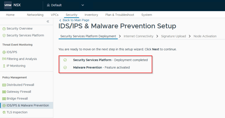
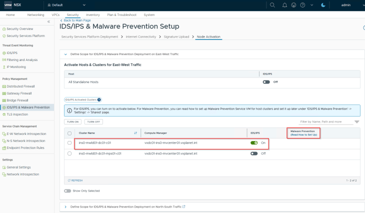
Our target workload cluster is ins0-mwld01-dc01-c01. Be careful not to select the sandboxing cluster (ins0-mwld01-dc01-mps01-c01) by mistake.
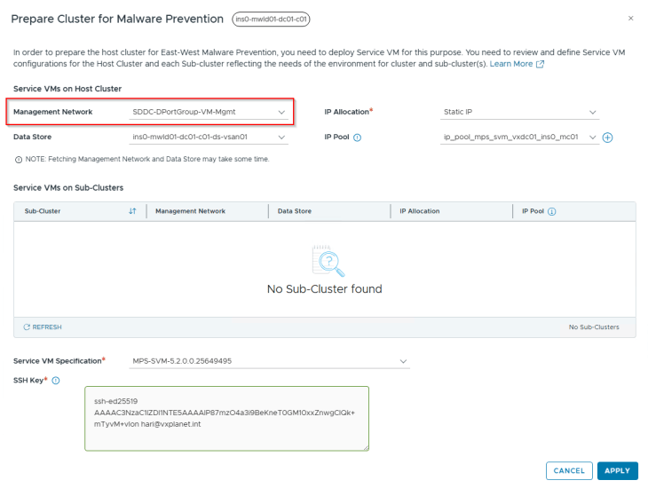
The SVMs require a management network that has connectivity to the SSP. I will select the VCF VM Management network as it has plenty of free IPs in it, and I can easily carve an IP pool out of it. We also need to provide an SSH public key from a jump host or admin station to enable passwordless SSH access to the SVMs for troubleshooting purposes.
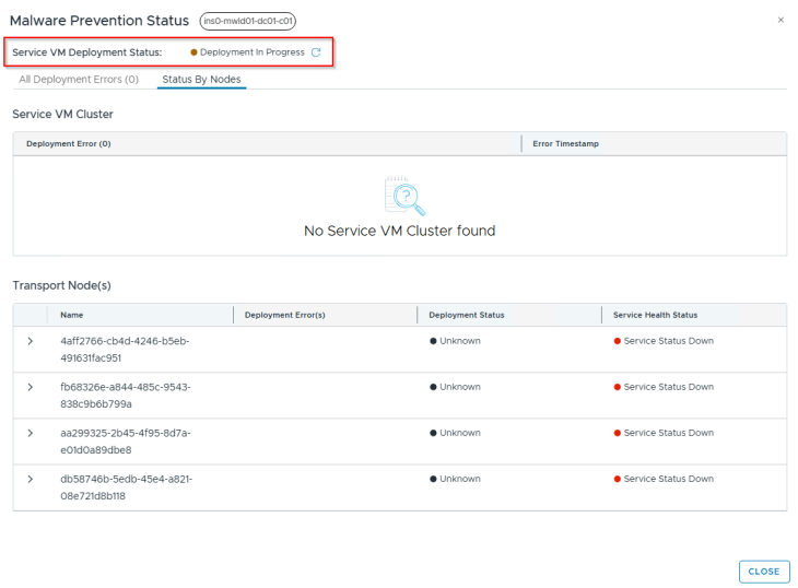
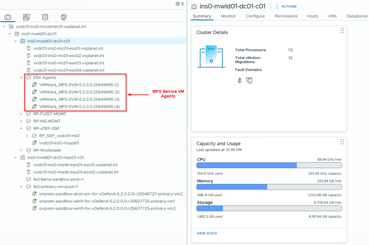
One SVM will be deployed per ESXi host within the workload cluster. We will wait for the deployment process to complete.
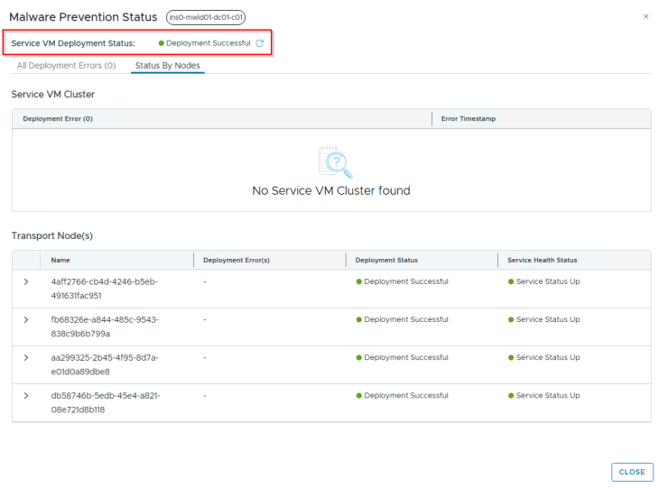
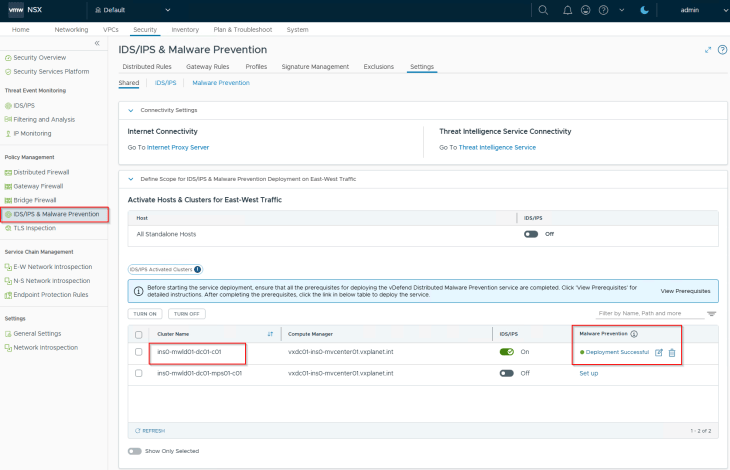
Once deployment is successful, we will see an SVM running on each host in the cluster.
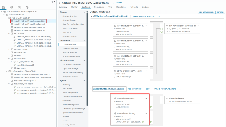
Each SVM also has an internal network connection called the control interface, used by the host hypervisor for securely transferring file introspection data to the SVM for local static analysis.
Excellent!!! We have now completed the activation of Distributed Malware Prevention Service & Sandboxing and deployed our SVMs. However, we haven’t actually tested this in action yet. We will pause here and resume in Part 3, where we will dive into threat detection, threat prevention policies, and testing. Stay tuned!
I hope the article was informative. Thanks for reading
Continue reading? Here are the other chapters of this series:
Part 1: Distributed Malware Prevention and Sandboxing Architecture
https://vxplanet.com/2026/09/20/distributed-malware-prevention-sandboxing-for-vcf-with-vmware-vdefend-part-1-architecture/